6.1 Wiring Main Circuit
6-7
(4)
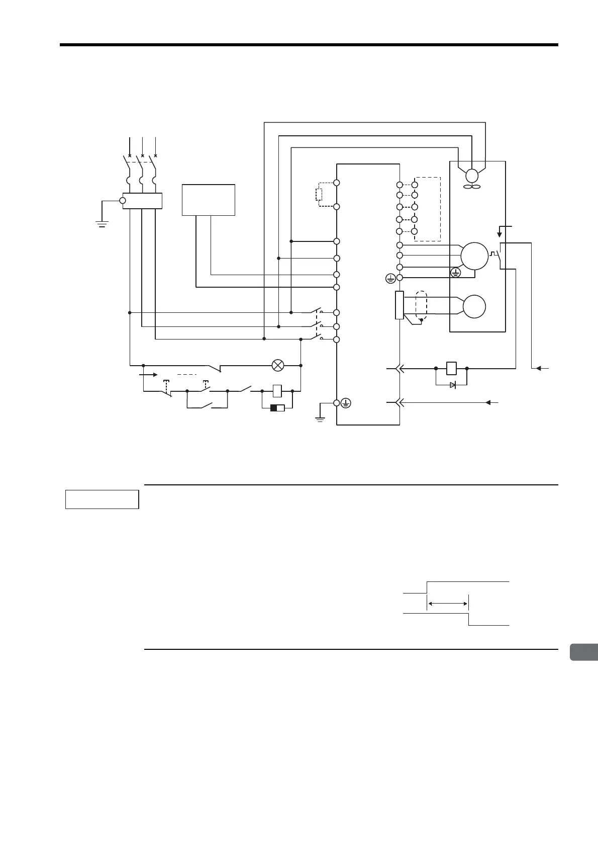
Three-phase 400 V, 37 kW to 90 kW SERVOPACKs
Designing a Power ON Sequence
Note the following points when designing the power ON sequence.
• Design the power ON sequence so that main circuit power supply is turned OFF when a servo alarm signal
is output. See the previous circuit figure.
• Hold the power ON button for at least two seconds. The SERVOPACK will output (1Ry is OFF) a servo
alarm signal for two seconds or less when power is turned ON. This is required in order to initialize the
SERVOPACK.
• Select the power supply specifications for the parts in accordance with the input power supply.
L1/R
DC24P
PG
U
V
W
M
+24V
0 V
24
1Ry
31
32
1D
OFF
1Ry
ON
1Ry
L2/S
L3/T
DC24N
B1
B2
DU
DV
DW
U(A)
V(B)
W(C)
1
1b
U
V
W
FG
FG
CN1
CN2
DB24
DBON
R ST
1PL
ALM -
ALM+
+10
-15
%
24 VDC
0V
380 to 480 V
SERVOPACK
SGDH- DEB
(Alarm lamp)
DB Unit
Fan
Main circuit
power
Thermal
protector
Three-phase
380 to 480 VAC
FIL
: Lamp for display
: Surge absorber
: Flywheel diode
1PL
1SA
1D
1QF
FIL
1KM
1Ry
: Circuit breaker (for inverters)
: Noise filter
: Contactor
: Relay
Prepared by customer
Control power
supply
+−
1SA
1KM
1KM
1KM
1QF
Power supply
Servo alarm (ALM)
output signal
2.0 s max.
Artisan Technology Group - Quality Instrumentation ... Guaranteed | (888) 88-SOURCE | www.artisantg.com

 Loading...


