11 Appendix
11.1.1 Selection Example for Speed Control
11-2
11.1 Servomotor Capacity Selection Examples
11.1.1 Selection Example for Speed Control
l
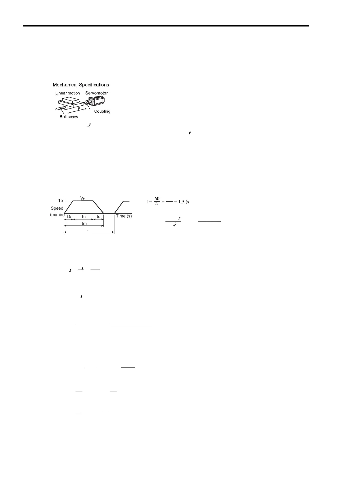
(1) Speed Diagram
(2) Rotation Speed
• Load axis rotation speed
• Motor shaft rotation speed with the direct coupling: Gear ratio 1/R = 1/1
Therefore,
(3) Load torque
(4) Load Moment of Inertia
• Linear motion section
• Ball screw
• Coupling
• Load moment of inertia at motor shaft
• Load speed: V = 15 m/min • Feeding times: n = 40 times/min
• Linear motion section mass: M = 500 kg
• Feeding distance: = 0.275 m
• Ball screw length: L
B
= 1.4 m • Feeding time: tm = 1.2 s max.
• Ball screw diameter: D
B
= 0.04 m • Friction coefficient: μ = 0.2
• Ball screw lead: P
B
= 0.01 m • Mechanical efficiency: η = 0.9 (90%)
• Coupling mass: M
C
= 1 kg
• Coupling outer diameter: D
C
= 0.06 m
1
Ball screw
Servomotor
Linear motion
Coupling
Mechanical Specifications
c
tt
a
d
t
(m/min)
Speed
Time (s)
tm
t
V
15
60
n
t = = = 1.5 (s)
tc = 1.2 − 0.1 × 2 = 1.0 (s)
where ta = td
60
40
60 ×
ta = tm − = 1.2 − = 0.1 (s)
60 × 0.275
15
V
N = = = 1500 (min )
V
15
P
B
-1
0.01
N = N R = 1500 × 1 = 1500 (min )
M
-1
T
L
= = = 1.73 (Nm)
9.8μ
M P
B
2πR η
9.8 × 0.2 × 500 × 0.01
2π × 1 × 0.9
J
L1
= M
(
)
2
= 500 ×
(
)
2
= 12.7 × 10
-4
(kg m
2
)
P
B
2πR
0.01
2π × 1
J = ρ L D = × 7.87 × 10 × 1.4 × (0.04) = 27.7 × 10 (kg m )
π
32
π
32
BBB
-4-344
2
J = M
C
D
C
2
= × 1 × (0.06)
2
= 4.5 × 10
-4
(kg
m
2
)
8
1
1
8
C
J = J +
J +
J = 44.9 × 10 (kg
m )
L
L1
C
B
-4 2
Artisan Technology Group - Quality Instrumentation ... Guaranteed | (888) 88-SOURCE | www.artisantg.com

 Loading...


