1.2 Examples of Servo System Configurations
1-3
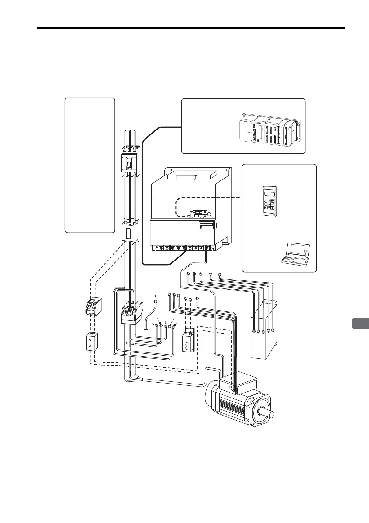
1.2 Examples of Servo System Configurations
This section describes examples of basic servo system configuration.
1.2.1 Three-phase, 200 V Series
U
V
W
B1
B2
RST
CN3
CN1
DB24
DU
DV
DW
DBON
DB24
DU
DV
DW
DBON
Regenerative
Resistor Unit
Power supply for
cooling fan
Power supply
Three-phase 200 VAC
SGMVH
servomotor
SGDM/SGDH SERVOPACK
Host controller
Connect the SGDM/SGDH SERVOPACK
to a Yaskawa or an other manufacturer’s
host controller.
Digital Operator
Allows the user to set parameters or
operation reference and display
operation status or alarm status.
(JUSP-OP02A-2)
Cable model:
Personal computer
Hand-held type
1-meter cable included
Molded-case circuit
breaker (MCCB)
Used to protect power
supply line.
Noise filter
Used to eliminate exter-
nal noise from power
supply line.
Magnetic contactor *
Turns the servo ON or
OFF.
Brake power supply
Used for SGMVH
servomotor with brake.
LPSE-2H01
(For 200 V input)
Dynamic Brake (DB)
Unit
*
Use a surge absorber
for the magnetic contactor.
Brake power supply
Dynamic Brake Unit
Used if dynamic brake
function is required for the
SERVOPACK.
Note: The Dynamic Brake (DB) Unit DBON and
DB24 terminals can be used with SERVO-
PACKs of 37 kW or more only.
MP900/MP2000 Series
JZSP-CMS01 to 03
L1/R
L2/S
L3/T
L3C/t
L1C/r
- +1
+2 L1/R L2/S L3/T
UVW
CN2
CN3
CN1
TDATA/SEEMOD/
SERVOPACK
YAS KAWA
R
O
P
E
R
A
T
O
CN3
8CN
POWER
CN5
SGDH-
㧖㧖㧖㧖
Artisan Technology Group - Quality Instrumentation ... Guaranteed | (888) 88-SOURCE | www.artisantg.com

 Loading...


