6.3 I/O Signal Connections
6-11
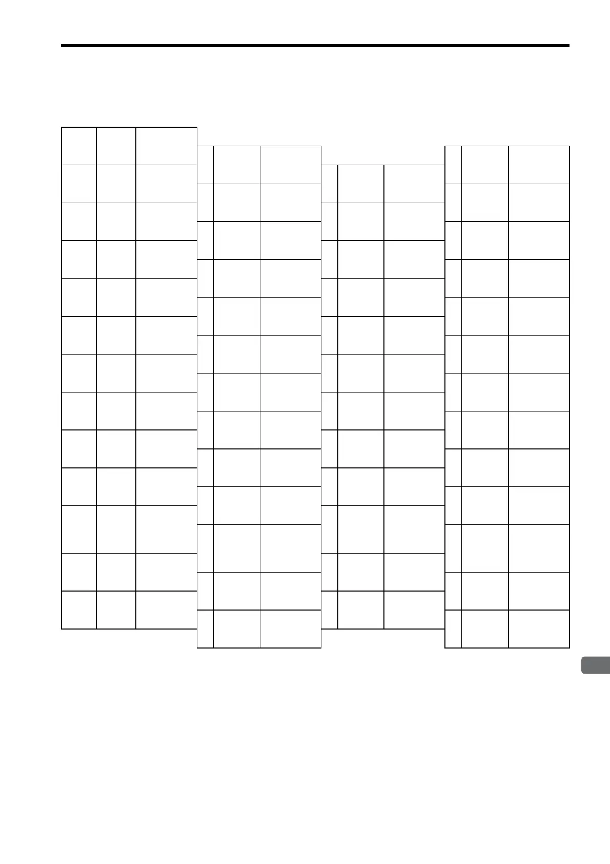
6.3.2 I/O Signal Connector (CN1) Terminal Layout
The following diagram shows the terminal layout and the signals that are preset before shipping.
Notes: 1. Do not use unused terminals for relays.
2. Connect the shield of the I/O signal cable to the connector shell.
Connect to the FG (frame ground) at the SERVOPACK-end connector.
3. The functions allocated to the following input and output signals can be changed by using the
parameters.
• Input signals: /S-ON, /P-CON, P-OT, N-OT, /ALM-RST, /P-CL, and /N-CL
• Output signals: /TGON, /S-RDY, and /V-CMP (/COIN)
• The above output signals can be changed to /CLT, /VLT, /BK, /WARN, and /NEAR.
Pin
Num-
ber
Signal
Name
Function
1
SG GND
26
/V-CMP-
(/COIN-)
Speed coinci-
dence detec-
tion output
2
SG GND
27
/TGON+
Running sig-
nal output
3
PL1
Open-collec-
tor reference
power supply
28
/TGON-
Running
signal output
4
SEN
SEN signal
input
29
/S-RDY+
Servo ready
output
5
V-REF
Speed refer-
ence input
30
/S-RDY-
Servo ready
output
6
SG GND
31
ALM+
Servo alarm
output
7
PULS
Reference
pulse input
32
ALM-
Servo alarm
output
8
/PULS
Reference
pulse input
33
PAO
PG dividing
pulse output
Phase A
9
T-REF
Torque refer-
ence input
34
/PAO
PG dividing
pulse output
Phase A
10
SG GND
35
PBO
PG dividing
pulse output
Phase B
11
SIGN
Reference
sign input
36
/PBO
PG div
iding
pulse output
Phase B
12
/SIGN
Reference
sign input
37
ALO1
Alarm code
output
13
PL2
Open-collec-
tor reference
power supply
38
ALO2
Alarm code
output
14
/CLR Clear input
39
ALO3
Alarm code
output
15
CLR Clear input
40
/S-ON
Servo ON
input
16
−−
41
/P-CON
P control
input
17
−−
42
P-OT
Forward run
prohibit input
18
PL3
Open-collec-
tor reference
power supply
43
N-OT
Reverse run
prohibit input
19
PCO
PG dividing
pulse output
Phase C
44
/ALM-
RST
Alarm reset
input
20
/PCO
PG dividing
pulse output
Phase C
45
/P-CL
Forward
external
torque limit
input
21
BAT (+) Battery (+)
46
/N-CL
Reverse
external
torque limit
input
22
BAT (-) Battery (-)
47
+24V
IN
External input
power supply
23
−−
48
PSO
Phase-S
signal output
24
−−
49
/PSO
Phase-S
signal output
25
/V
-CMP+
(/COIN+)
Speed coinci-
dence detec-
tion output
50
−−
Artisan Technology Group - Quality Instrumentation ... Guaranteed | (888) 88-SOURCE | www.artisantg.com

 Loading...


