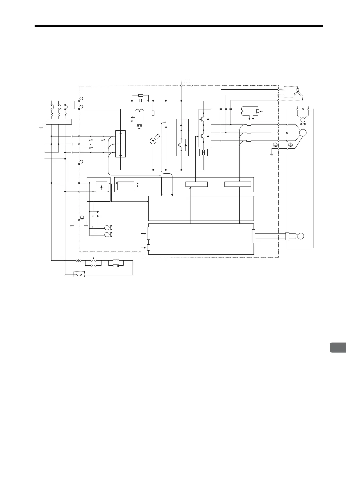
4.3 SERVOPACK Internal Block Diagrams
4
SERVOPACK Specifications and Dimensional Drawings
4-7
4.3 SERVOPACK Internal Block Diagrams
4.3.1
Three-phase 200 V, 22 kW, 30 kW Models
FIL
R
S
T
1KM
L1/R
+ 1
+ 2
R1
B1
TRM7
TRM1 to
TRM6
FU1 to 3
C1 to
C4
B2
+
-
CHARGE
SA1 to SA3
3PWB
200 VAC
1KM
1KM
(5Ry) Open during servo alarm
1CN
3CN
L1C/r
L3C/t
+5V
2PWB
2CN
PG
L2/S
L3/T
-
200 VAC
DCCT1
DCCT2
DCCT3
MC2
DU
DV
DW
U
V
W
U
RST
UVW
V
W
M
200
VAC
MC1
MC1
FAN
㨪ޓ
㨪ޓ
FAN1 to FAN2
1QF
Servomotor
Three-phase
200 to 230 VAC
(50/60 Hz)
Regenerative resistor (option)
DB resistor (option)
From
detection
circuit
From detection
circuit
DC/DC
converter
Power for
drive
Drive circuit
Current sensor
Sensor circuit
Position/speed calculation circuit
Control input
Digital operator
(personal computer)
Power OFF
Power ON
Surge absorber
Artisan Technology Group - Quality Instrumentation ... Guaranteed | (888) 88-SOURCE | www.artisantg.com

 Loading...


