8.6 Operating Using Position Control
8-49
8.6 Operating Using Position Control
8.6.1 Setting Parameters
Set the following parameters for position control using pulse trains.
(1) Control Mode Selection
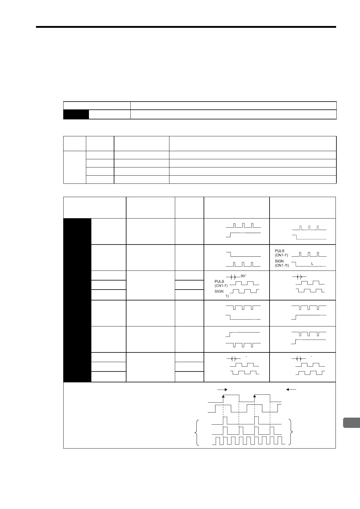
(2) Setting a Reference Pulse Form
Set the input form for the SERVOPACK using parameter Pn200.0 according to the host controller specifications.
Parameter Meaning
Pn000
n.
1
Control mode selection: Position control (pulse train reference)
Type
Signal
Name
Connector
Pin Number
Name
Input
PULS CN1-7 Reference Pulse Input
/PULS CN1-8 Reference Pulse Input
SIGN CN1-11 Reference Code Input
/SIGN CN1-12 Reference Code Input
Parameter
Reference Pulse
Form
Input
Pulse
Multiplier
Forward Rotation
Reference
Reverse Rotation
Reference
Pn200
n.
0
Sign + pulse train
(Positive logic)
(Factory setting)
−
n.
1
CW pulse + CCW
pulse
(Positive logic)
−
n.
2
Two-phase pulse
train with 90° phase
differential
(Positive logic)
×1
n.
3
×2
n.
4
×4
n.
5
Sign + pulse train
(Negative logic)
−
n.
6
CW pulse + CCW
pulse
(Negative logic)
−
n.
7
Two-phase pulse
train with 90° phase
differential
(Negative logic)
×
1
n.
8
×
2
n.
9
×
4
The input pulse multiplier can be set for the
2-phase pulse train with 90° phase differen-
tial reference pulse form.
(CN1-7)
(CN1-11)
PULS
SIGN
Internal
processing
×1
×2
×4
Motor movement
reference pulses
Forward rotation
Reverse rotation
Artisan Technology Group - Quality Instrumentation ... Guaranteed | (888) 88-SOURCE | www.artisantg.com

 Loading...


