11.2 Connection to Host Controller
11-11
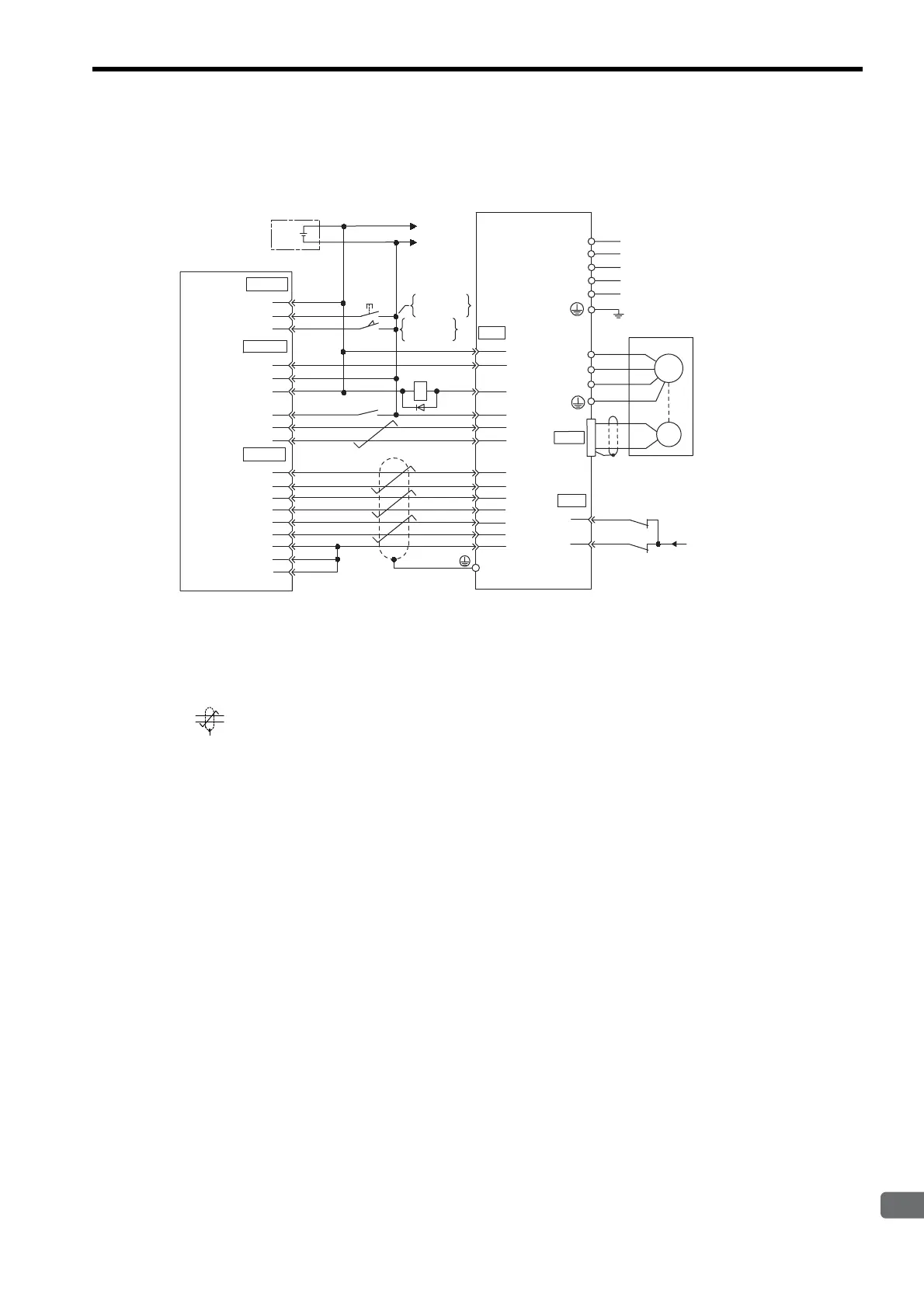
11.2.5 Example of Connection to MITSUBISHI’s AD72 Positioning
Unit (SERVOPACK in Speed Control Mode)
* 1. The ALM signal is output for about two seconds after the power is turned ON. Take this into consid-
eration when designing the power ON sequence. The ALM signal actuates the alarm detection relay
1Ry to stop the main circuit power supply to the SERVOPACK.
* 2. Pin numbers are the same both for X-axis and Y-axis.
* 3. Connect the connector wire to the connector shell.
* 4. represents twisted-pair wires.
Note: Only signals applicable to Mitsubishi’s AD72 Positioning Unit and Yaskawa’s SGDM/SGDH
SERVOPACK are shown in the diagram.
43
42
1Ry
+
-
+24V
I/O power supply
0
24
V
+24 V
CONT
SERVO
CN1
ENCO
CN1
STOP
DOG
SV-ON
READY
PULSE A
PULSE C
PULSE B
0V
0V
0V
∗
2
1
3
2
1
3
2
4
6
5
4
7
5
8
11
10
3
9
6
1
+24V-IN
P-OT
N-OT
ALM+
ALM-
V-REF (T-REF)
SG
PAO
SG
/PCO
PCO
/PBO
PBO
/PAO
47
32
31
40
1
20
19
34
33
36
35
5
(9)
6
(10)
/S-ON
1Ry
∗
4
0
24
V
Positioning unit AD72
manufactured
by Mitsubishi
SGDM/SGDH SERVOPACK
Speed reference
ON when
positioning is
canceled.
ON when
proximity is
detected.
∗3
Connector
shell
CN2
W
V
A(1)
B
(2)
C
(3)
D
(4)
U
Servomotor
M
Control
power supply
PG
Main circuit
power supply
L1C/r
L3/T
L2/S
L1/R
L2C/t
Artisan Technology Group - Quality Instrumentation ... Guaranteed | (888) 88-SOURCE | www.artisantg.com

 Loading...


