11 Appendix
11.1.2 Selection Example for Position Control
11-4
(9) Result
The provisionally selected servomotor and SERVOPACK are confirmed to be applicable.
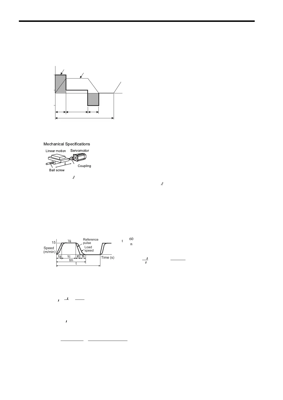
The torque diagram is shown below.
11.1.2 Selection Example for Position Control
(1) Speed Diagram
(2) Rotation Speed
• Load axis rotation speed
• Motor shaft rotation speed with direct coupling: Gear ratio 1/R = 1/1
Therefore,
(3) Load Torque
(Nm)
0.1
1.5
1.0
0.1
-7.5
0
1.73
11
Torque
Speed
• Load speed: V = 15 m/min • Positioning times: n = 40 times/min
• Linear motion section mass: M = 80 kg • Positioning distance: = 0.25 m
• Ball screw length: L
B
= 0.8 m • Positioning time: tm = Less than 1.2 s
• Ball screw diameter: D
B
= 0.016 m • Electrical stop accuracy: δ = ± 0.01 mm
• Ball screw lead: P
B
= 0.005 m • Friction coefficient: μ = 0.2
• Coupling mass: M
C
= 0.3 kg • Mechanical efficiency: η = 0.9 (90%)
• Coupling outer diameter: D
C
=0 .03 m
Where ta = td, ts = 0.1 (s)
1
Ball screw
Servomotor
Linear motion
Coupling
Mechanical Specifications
Load
speed
Reference
pulse
s
t
d
tt
a
c
t
(m/min)
Speed
Time (s)
tm
t
V
15
t
60
n
------
60
40
------1.5s()===
ta = tm − ts − = 1.2 − 0.1 − = 0.1 (s)
60
60 × 0.25
V
15
tc 1.2 0.1–0.12×–0.9s()==
N = = = 3000 (min )
V
15
P
B
-1
0.005
N = N R = 3000 × 1 = 3000 (min )
M
-1
T
L
= = = 0.139 (Nm)
9.8μ
M P
B
2πR η
9.8 × 0.2 × 80 × 0.005
2π × 1 × 0.9
Artisan Technology Group - Quality Instrumentation ... Guaranteed | (888) 88-SOURCE | www.artisantg.com

 Loading...


