11 Appendix
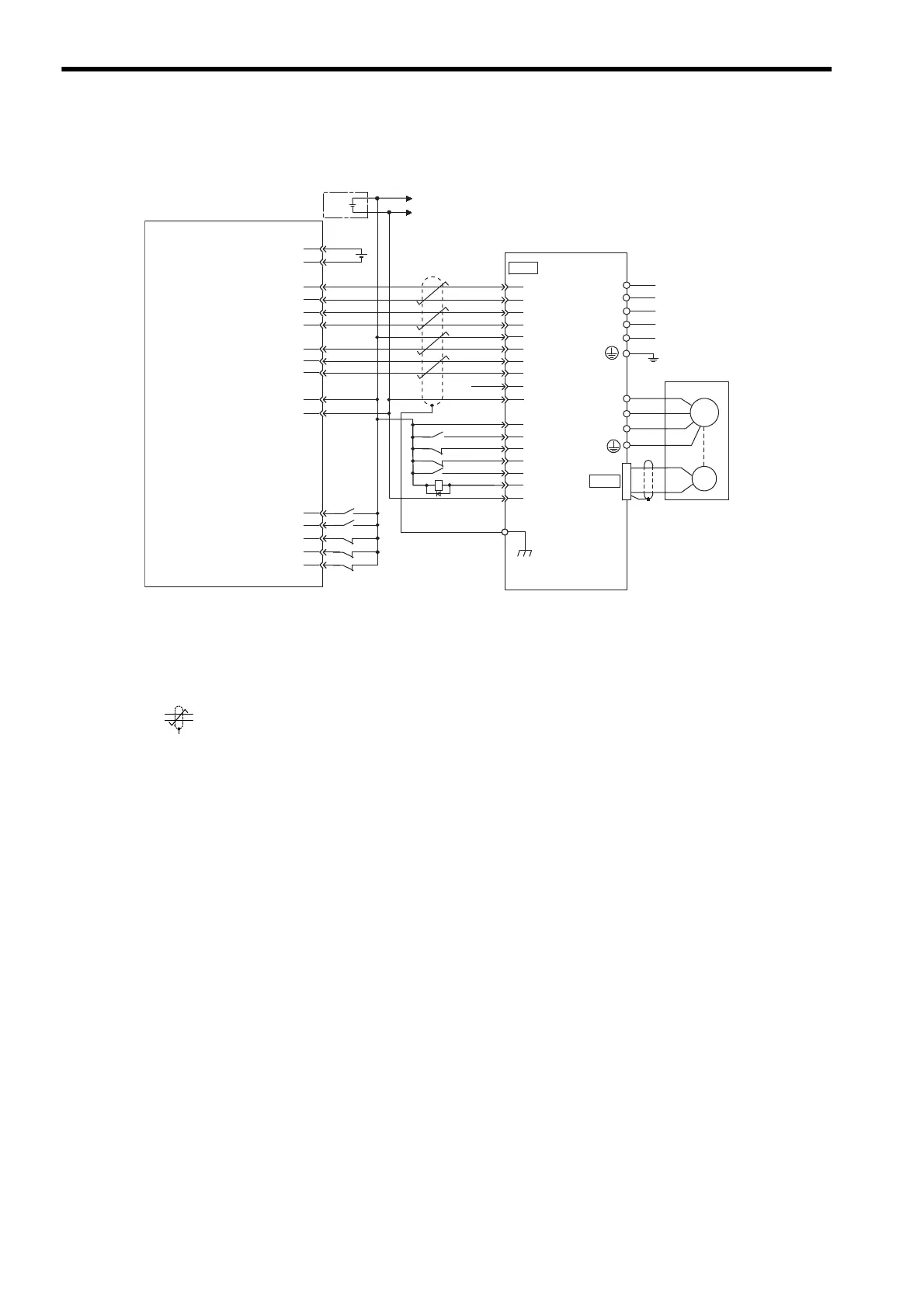
11.2.4 Example of Connection to OMRON’s Position Control Unit
11-10
11.2.4 Example of Connection to OMRON’s Position Control Unit
* 1. The ALM signal is output for about two seconds after the power is turned ON. Take this into consid-
eration when designing the power ON sequence. The ALM signal actuates the alarm detection relay
1Ry to stop the main circuit power supply to the SERVOPACK.
* 2. Set parameter Pn200.0 to 1.
* 3. Connect the shield wire to the connector shell.
* 4. represents twisted-pair wires.
Note: Only signals applicable to OMRON’s MC unit (positioning unit) and Yaskawa’s SGDM/SGDH
SERVOPACK are shown in the diagram.
CN2
CN1
A3
A5
A6
A7
A4
8
20
25
19
12
7
14
15
W
V
A(1)
B
(2)
C
(3)
D
(4)
U
Position control unit
Servomotor
SGDM/SGDH
SERVOPACK
CS1W-NC133 / 233 / 433
manufactured by OMRON
A16
A11
A14
A1
A2
A8
A20
A22
A23
A21
A19
11
/SIGN
CLR
/CLR
PCO
PULS
/PULS
SIGN
/PCO
COIN+
/COIN-
26
31
32
44
42
43
47
40
+24V-IN
/S-ON
P-OT
N-OT
/ALM-RST
ALM-
ALM+
1Ry
1
2
3
4
5 VDC
5V power supply for pulse output
5V GND for pulse output
24 V power supply for output
24 V GND for output
CCW(+) output
CCW(-) output
CW(+) output
CW(-) output
Origin input signal
Origin input common
Error counter reset output
X-axis CW limit input
X-axis CCW limit input
X-axis immediate stop input
X-axis origin proximity input
X-axis external interrupt input
Connector
shell
M
Control
power supply
Main circuit
power supply
PG
+
-
+24V
0
24
+24
V
I/O power supply
L1C/r
L3/T
L2/S
L1/R
L2C/t
Artisan Technology Group - Quality Instrumentation ... Guaranteed | (888) 88-SOURCE | www.artisantg.com

 Loading...


