4.3 SERVOPACK Internal Block Diagrams
4
SERVOPACK Specifications and Dimensional Drawings
4-9
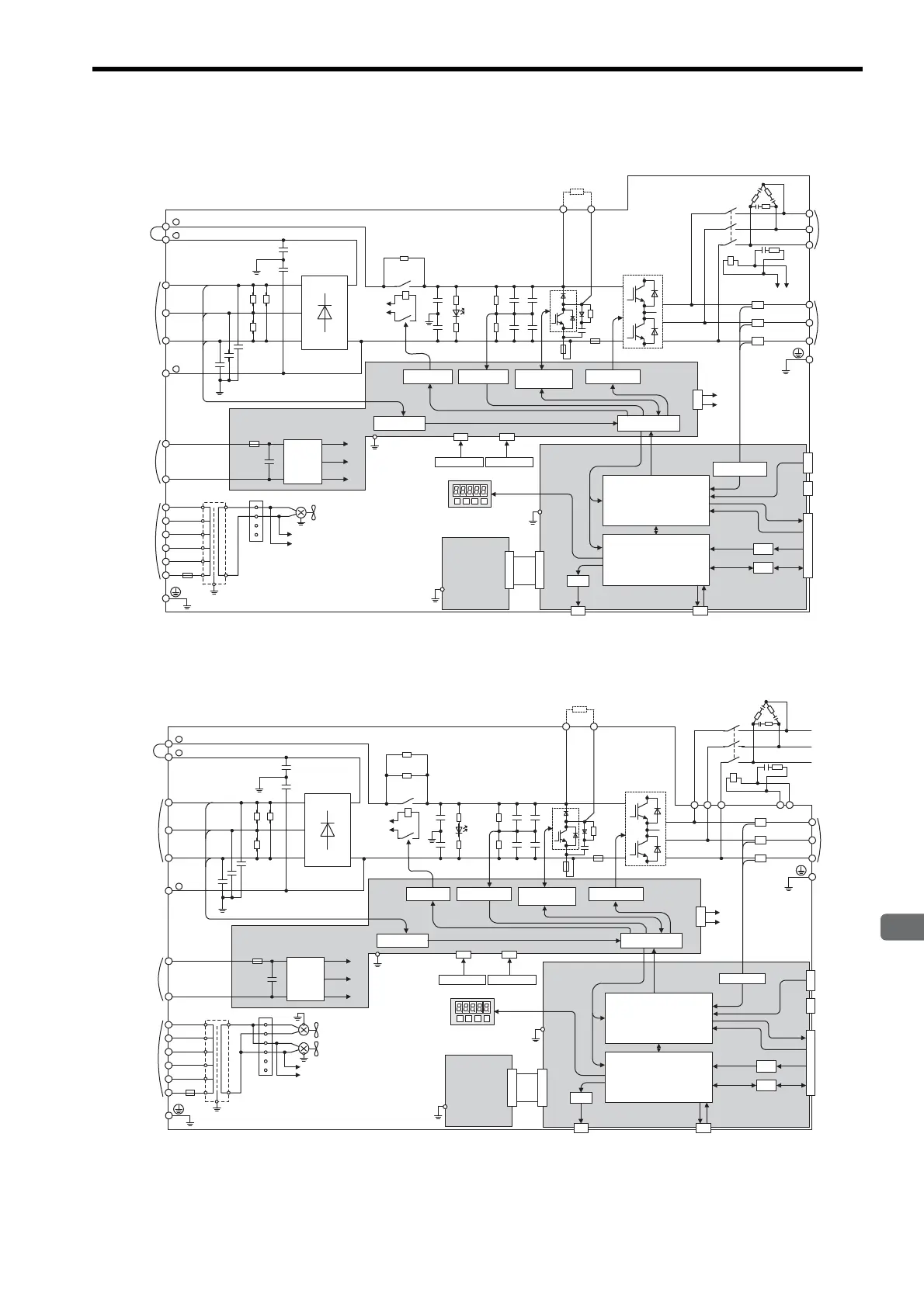
4.3.3
Three-phase
400 V, 22 kW, 30 kW Models
4.3.4
Three-phase
400 V, 37 kW Model
D/A
A/D
I/O
CN5 CN3
CN10
CN2
CN8
CN1
1PCB
2PCB
+
-
+5V
+24V
+15V
43CN
3PCB
200 VAC
FAN1
215V
1
2
3
4
480V
460V
440V
400V
380V
0V
600V 4A
0
E
DC24P
DC24N
DU
DV
DW
MC2
DCCT1
DB24DBON
W
V
U
W
V
U
DCCT2
DCCT3
DB24
DBON
R
T
S
+
-
+
-
+
-
+
-
TRM1 to TRM6
C1 to C4
TRM7
+
-
+
-
CHARGE
MC1
MC1
R1
200 VAC
C64
C65
C61 to C63
L1/R
DM1
to DM3
PG
1
2
-
L2/S
L3/T
B1 B2
+
+
FU1
FU4
MC2
SA1 to SA3
Digital operator
DC reactor
connection
terminals
Main circuit power
input terminals
(380 to 480 VAC)
Main circuit
minus terminal
Control power
input terminals
(24 VDC)
Control power
input terminals
(380 to 480 VAC)
Ground terminal
Ground terminal
VaristorVaris to r
Varistor
DC/DC
converter
Voltage sensor
Relay drive Voltage sensor
Voltage sensor
gate drive
Gate drive
Interface
Regenerative resistor
Regenerative resistor
unit connection terminals
Motor
connection
terminals
Thermostat 1 Thermostat 2
Panel operator
(Option unit)
ASIC (PWM control, etc.)
CPU
(Position/speed calculation, etc.)
Current sensor
Battery
PG output
Reference pulse
input
Speed/torque
reference input
Sequence input
Analog monitor
Dynamic
brake
unit
connection
terminals
D/A
A/D
I/O
CN5 CN3
CN10
CN2
CN8
CN1
1PCB
2PCB
+
-
+5V
+24V
+15V
43CN
3PCB
DC24P
DC24N
DU
DV
DW
KM
DCCT1
DB24
DBON
W
V
U
W
V
U
DCCT2
DCCT3
DB24
DBON
R
T
S
+
-
+
-
+
-
+
-
TRM1 to TRM6
C1 to C4
TRM7
+
-
+
-
CHARGE
MC1
MC1
R1
200 VAC
DM1 to DM3
C64
C65
C61 to C63
L1/R
1
2
-
L2/S
L3/T
B1 B2
+
+
FU1
FU4
FAN1
215V
1
2
3
4
480V
460V
440V
400V
380V
0V
600V 4A
0
E
FAN2
5
6
200 VAC
SA1 to SA3
DU DV DW
KM
R2
Panel operator
PG
Digital operator
DC reactor
connection
terminals
Main circuit power
input terminals
(380 to 480 VAC)
Main circuit
minus terminal
Control power
input terminals
(24 VDC)
Control power
input terminals
(380 to 480 VAC)
Ground terminal
Ground terminal
Varistor
VaristorVaris to r
DC/DC
converter
Voltage sensor
Relay drive
Voltage sensor
Voltage sensor
gate drive
Gate drive
Interface
Regenerative resistor
Regenerative resistor
unit connection terminals
Motor
connection
terminals
Thermostat 1
Thermostat 2
(Option unit)
ASIC (PWM control, etc.)
CPU
(Position/speed calculation, etc.)
Battery
PG output
Reference pulse
input
Speed/torque
reference input
Sequence input
Analog monitor
Current sensor
Artisan Technology Group - Quality Instrumentation ... Guaranteed | (888) 88-SOURCE | www.artisantg.com

 Loading...


