4.2 SERVOPACK Installation
4
SERVOPACK Specifications and Dimensional Drawings
4-5
4.2 SERVOPACK Installation
The SGDM/SGDH SERVOPACKs can be mounted on a base. Incorrect installation will cause problems. Always
observe the following installation instructions.
• After voltage resistance test, wait at least five minutes before servicing the product. (Refer to “Voltage Resis-
tance Test” on the following page.)
Failure to observe this warning may result in electric shock.
• Connect the main circuit wires, control wires, and main circuit cables of the motor correctly.
Incorrect wiring will result in failure of the SERVOPACK.
Storage Store the SERVOPACK within the following temperature range if it is stored with the power cable discon-
nected.
Temperature: -20 to 85°C
Humidity: 90% RH or less (with no condensation)
Installation Site Installation in a Control Panel
Design the control panel size, unit layout, and cooling method so the temperature around the SERVOPACK
does not exceed 55°C.
Installation Near a Heating Unit
Minimize the heat radiating from the heating unit as well as any temperature rise caused by natural convec-
tion so the temperature around the SERVOPACK does not exceed 55 °C.
Installation Near a Source of Vibration
Install a vibration isolator on the SERVOPACK to avoid subjecting it to vibration.
Installation at a Site Exposed to Corrosive Gas
Corrosive gas does not have an immediate effect on the SERVOPACK but will eventually cause the elec-
tronic components and contactor-related devices to malfunction. Take appropriate action to avoid corrosive
gas.
Other Situations
Do not install the SERVOPACK in hot, humid locations or locations subject to water, cutting oil, excessive
dust, iron powder, and radioactivity in the air.
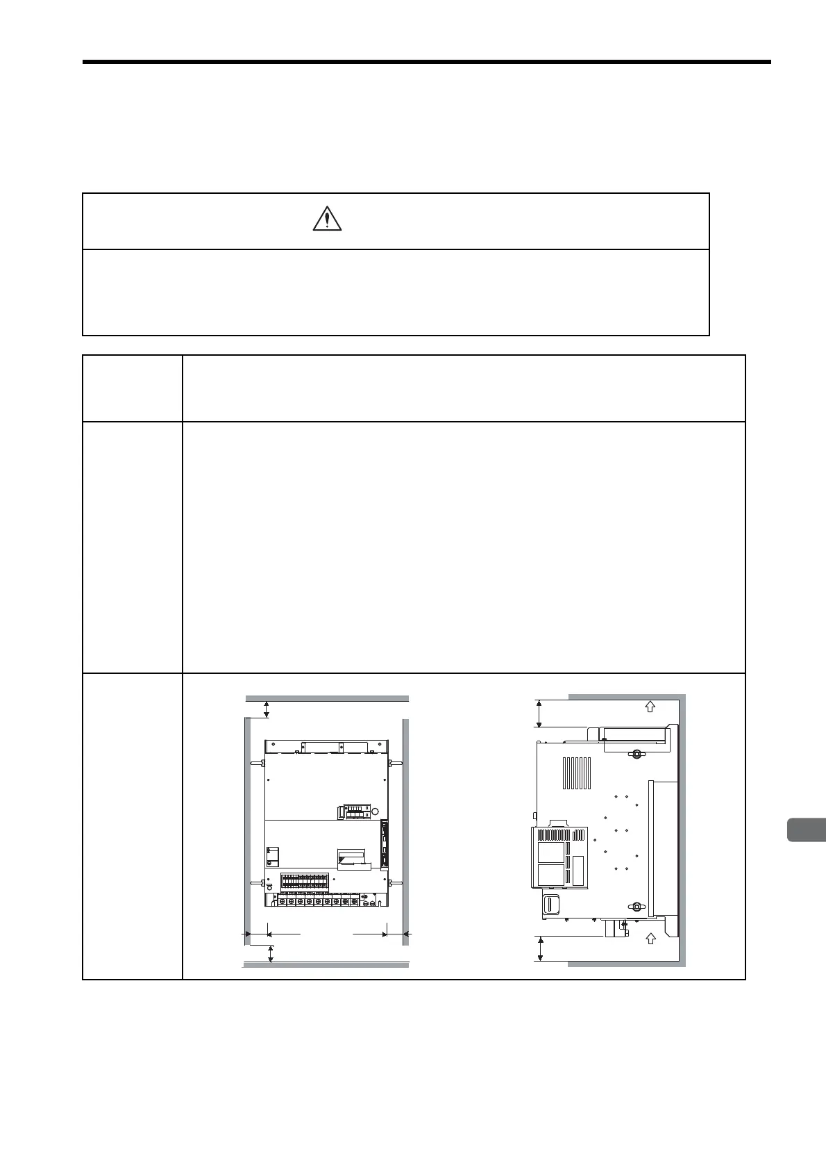
Orientation Install the SERVOPACK perpendicular to the wall as shown in the figure.
Air flow
120 mm min.
120 mm min.
Air flow
50 mm min.
(ventilation exhaust)
50 mm min. (ventilation intake)
50 mm min.
50 mm min.
+2-+1
L1/R L2/S
L3/T
UVW
480
V
460
V
DU
400
V
0
V
440
V
DWDV B1
380
V
DC
24N
B2
DC
24P
CHARGE
S-HDG
㧖㧖㧖㧖
T DATA/SEEMOD/
KSERVOPAC
AYASKAW
R
O
P
E
R
A
T
O
CN3
8CN
POWER
CN5
WARNING
ෂޓ㒾
ㅢ㔚߮㔚Ḯࠝࡈᓟ5
ಽ㑆ޔ┵ሶㇱߦ⸅ࠆߥ!
electric shock.
Disconnect all power
May cause
ᗵ㔚ߩᕟࠇࠅ
before servicing.
and wait 5 min.
grounding techniques.
ធ⛯ߖࠃ
Use proper
ᔅߕࠕ㧙ࠬ✢ࠍ
Artisan Technology Group - Quality Instrumentation ... Guaranteed | (888) 88-SOURCE | www.artisantg.com

 Loading...


