6.3 I/O Signal Connections
6-15
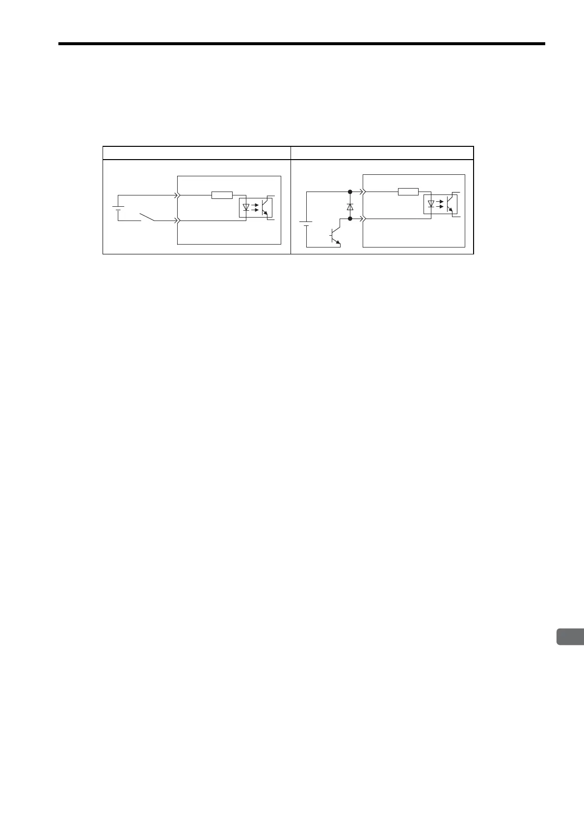
(2) Sequence Input Circuit Interface
CN1 connector terminals 40 to 47 is explained below.
The sequence input circuit interface connects through a relay or open-collector transistor circuit. Select a low-
current relay otherwise a faulty contact will result.
Note: The 24 VDC external power supply capacity must be 50 mA minimum.
(3) Output Circuit Interface
There are three types of SERVOPACK output circuits:
(a) Line Driver Output Circuit
CN1 connector terminals, 33-34: phase-A signal, 35-36: phase-B signal and 19-20: phase-C signal are
explained below.
Encoder serial data converted to two-phase (phases A and B) pulse output signals (PAO, /PAO, PBO, /PBO),
zero-point pulse signals (PCO, /PCO), and the amount of phase-S rotation signal are output via line-driver
output circuits. Normally, the SERVOPACK uses this output circuit in speed control to comprise the position
control system at the host controller. Connect the line-driver output circuit through a line receiver circuit at
the host controller.
Relay Circuit Example Open-collector Circuit Example
3.3 kΩ
/S-ON, etc.
SERVOPACK
24 VDC
+24VIN
+24VIN
3.3 kΩ
/S-ON, etc.
SERVOPACK
24 VDC
Artisan Technology Group - Quality Instrumentation ... Guaranteed | (888) 88-SOURCE | www.artisantg.com

 Loading...


