8.6 Operating Using Position Control
8-53
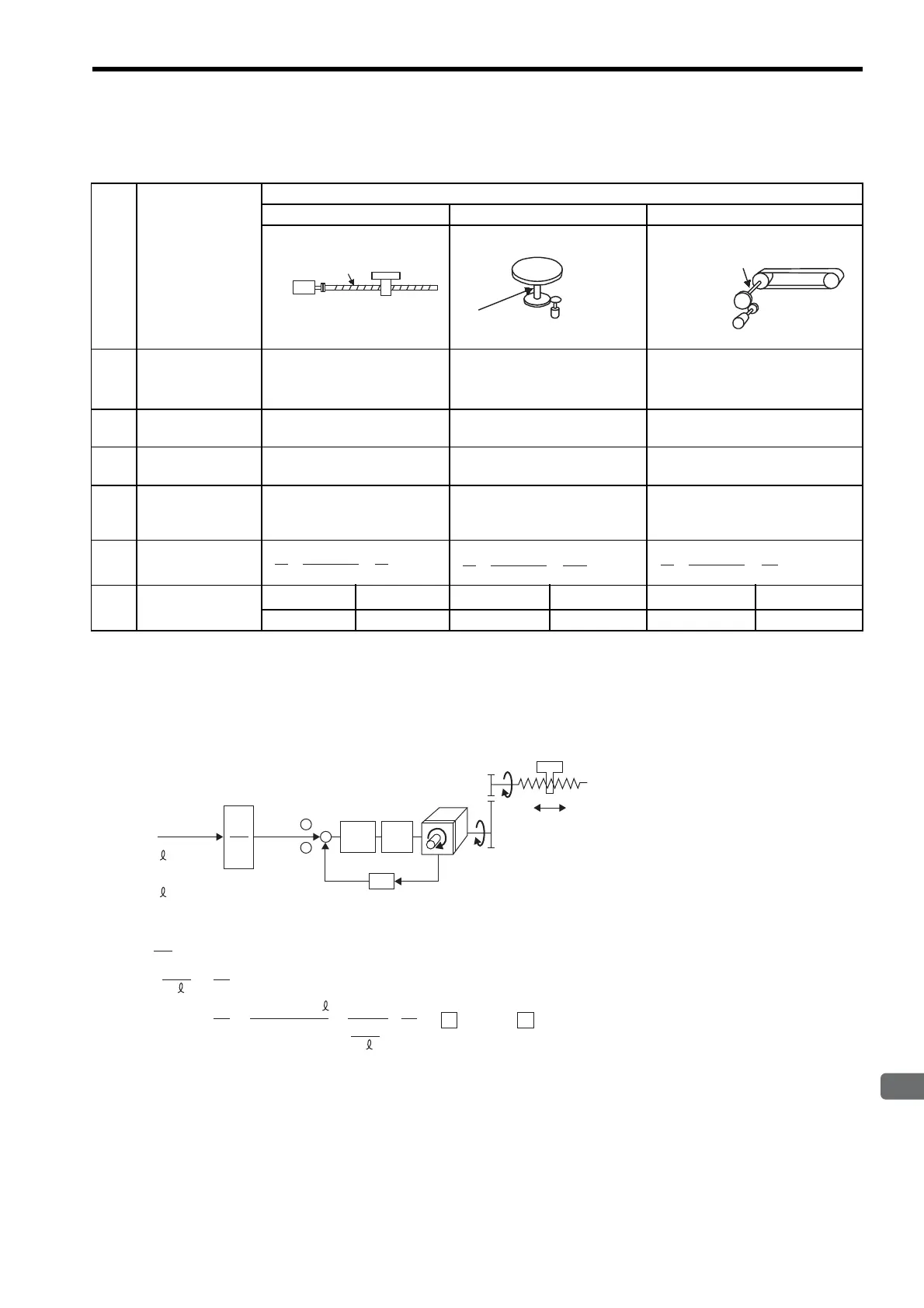
(5) Electronic Gear Ratio Setting Examples
The following examples show electronic gear ratio settings for different load configurations.
Reduce the fraction (both numerator and denominator) since the calculated result will not be within the setting
range. For example, reduce the numerator and denominator by four to obtain Pn201=32768, Pn203=3925 and
complete the settings.
(6) Electronic Gear Ratio Equation
Step Operation
Load Configuration
Ball Screw Disc Table Belt and Pulley
1
Check machine
specifications.
x
Ball screw pitch: 6 mm
x
Deceleration ratio: 1/1
Rotation angle per revolution:
360°
Deceleration ratio: 3/1
Pulley diameter: 100 mm
(pulley circumference: 314 mm)
x
Deceleration ratio: 2/1
2
Check the number
of encoder pulses.
13-bit: 2048 P/Rev 13-bit: 2048 P/Rev 16-bit: 16384 P/Rev
3
Determine the ref-
erence unit used.
1 Reference unit: 0.001 mm
(1 μm)
1 Reference unit: 0.1
°
1 Reference unit: 0.02 mm
4
Calculate the travel
distance per load
shaft revolution.
6 mm/0.001 mm=6000
360
°/0.1°=3600
314 mm/0.02 mm=15700
5
Calculate the elec-
tronic gear ratio.
6
Set parameters.
Pn202 8192 Pn202 24576 Pn202
131072
∗
Pn203 6000 Pn203 3600 Pn203 15700
Ball screw
pitch: 6 mm
13-bit encoder
Load shaft
Reference unit: 0.001 mm
13-bit encoder
Load shaft
Reference unit: 0.1°
Deceleration
ratio:
3 : 1
Load shaft
Deceleration
ratio
2 : 1
Reference Unit: 0.02 mm
Pully diameter:
100 mm
16-bit encoder
A
B
n
m
+
-
×4
Pitch = P (mm/rev)
m
n
Servomotor
P
G
(P/rev)
P
G
(P/Rev): Encoder pulses
Position
loop
Speed
loop
Reference pulse
Δ (mm/P)
n × P
n × P
B
Δ A
G
Δ (mm/P): Reference unit
P
Δ
Δ
×
×
()
m
n
= 4 × P × m
B
A
()
==
G G
4 × P × m × 4 × P
Set A and B with the following parameters.
A
㧦Pn203
B
㧦Pn202
P (mm/Rev): Ball screw pitch
: Deceleration ratio
Artisan Technology Group - Quality Instrumentation ... Guaranteed | (888) 88-SOURCE | www.artisantg.com

 Loading...


