8 Operation
8.6.8 Reference Pulse Input Multiplication Switching Function
8-62
Note: After changing the setting, turn OFF the power and ON again to enable the new setting.
(4) Output Signal Selection
The /PSELA signal is the output signal that indicates if switching for reference pulse input multiplication is
enabled by /PSEL signal or not.
The /PSELA signal can’t be used with the factory setting. Allocate the /PSELA output signal.
Note: After changing the setting, turn OFF the power and ON again to enable the new setting.
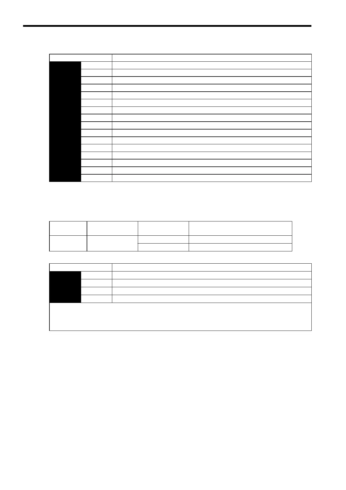
Parameter Description
Pn513 n.0 Input signal from CN1-40 is ON (high level): Enabled
n.1 Input signal from CN1-41 is ON (high level): Enabled
n.2 Input signal from CN1-42 is ON (high level): Enabled
n.3 Input signal from CN1-43 is ON (high level): Enabled
n.4 Input signal from CN1-44 is ON (high level): Enabled
n.5 Input signal from CN1-45 is ON (high level): Enabled
n.6 Input signal from CN1-46 is ON (high level): Enabled
n.7 Sets the signal ON.
n.8 Sets the signal OFF. (Factory setting)
n.9 Input signal from CN1-40 is OFF (low level): Enabled
n.A Input signal from CN1-41 is OFF (low level): Enabled
n.B Input signal from CN1-42 is OFF (low level): Enabled
n.C Input signal from CN1-43 is OFF (low level): Enabled
n.D Input signal from CN1-44 is OFF (low level): Enabled
n.E Input signal from CN1-45 is OFF (low level): Enabled
n.F Input signal from CN1-46 is OFF (low level): Enabled
Signal Name
Connector Pin
Number
Setting Meaning
/PSELA
Signal allocation not
required
ON (low level) Enabled when the /PSEL signal turns ON.
OFF (high level) Disabled when the /PSEL signal turns OFF.
Parameter Meaning
Pn510 n.0 Disabled (/PSELA output signal is not used.)
n.1 Outputs the /PSELA signal from the CN1-25, 26 output terminal.
n.2 Outputs the /PSELA signal from the CN1-27, 28 output terminal
n.3 Outputs the /PSELA signal from the CN1-29, 30 output terminal.
For the factory settings, the pins CN1-25 to CN1-30 are allocated for other output signals. If multiple signals are allocated
to the same output terminal, signals are output with OR logic. To enable only the /PSELA output signal, allocate the other
signals to other output terminals or disable the other signals.
Refer to 7.3.3 Output Circuit Signal Allocation for the allocation of output signals.
Artisan Technology Group - Quality Instrumentation ... Guaranteed | (888) 88-SOURCE | www.artisantg.com

 Loading...


