Communications D - 5
Message Format
In Modbus communication, the master sends commands to the slave, and the slave responds. The message format is
configured for both sending and receiving as shown below. The length of the data packets is changed by the command
(function) contents.
Fig. D.4 Message Format
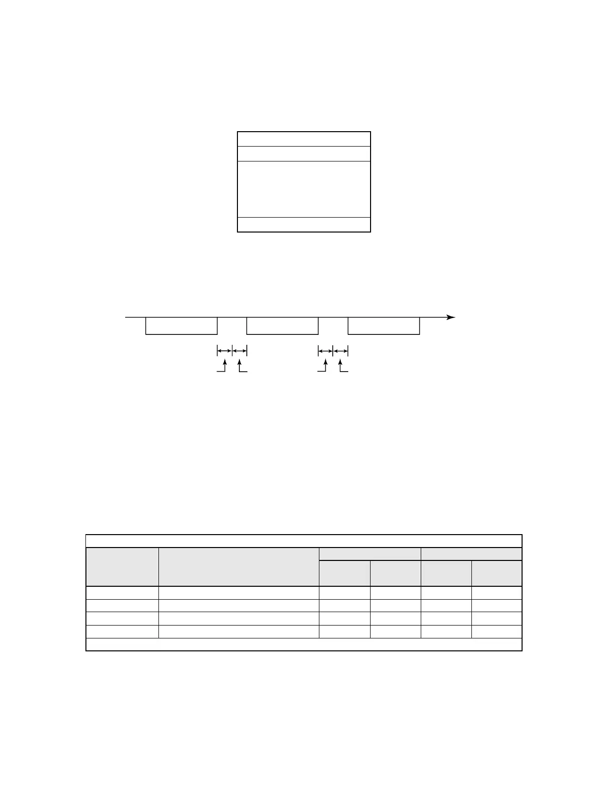
The space between messages must support the following:
Fig. D.5 Message Spacing
Slave Address
Set the Drive address from 0 to 32. If 0 is selected, commands from the master will be broadcast (i.e., the Drive will not return
responses).
Function Code
The function code specifies commands. There are four function codes, as shown below.
Data
Configure consecutive data by combining the storage register address (test code for a loopback address) and the data the
register contains. The data length changes depending on the command details.
Slave address
Function code
Data
Error check
Table D.3 Modbus Function Codes
Function Code
(Hexadecimal)
Function
Command Message Response Message
Min.
(Bytes)
Max.
(Bytes)
Min.*
(Bytes)
Max.
(Bytes)
03H Reading/Holding Register Contents 8 8 7 37
06H Write In Single Holding Register 8 8 8 8
08H Loopback Test 8 8 8 8
10H Write In Several Holding Registers 11 41 8 8
* Minimum bytes for a normal Response Message (error response message is always 5 bytes).
PLC to Drive
Drive to PLC
PLC to Drive
Command message
Response message
Command message
Time (Seconds)
24 bits long
5 ms min.
H5-06
setting
24 bits long