Electrical Installation 2 - 16
Terminal Connections
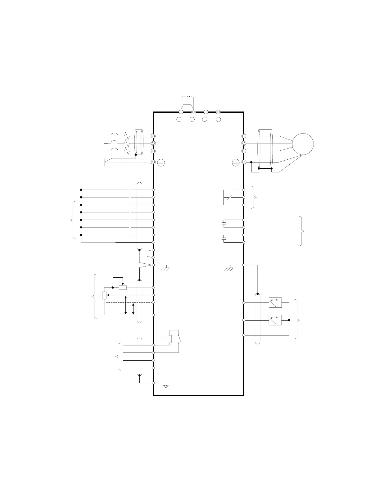
Connections to Drive terminals are shown in Fig 2.7.
Fig 2.7 Terminal Connections
T/L3
S/L2
R/L1
S3 (H1-01)
S2
S1
SC
E(G)
SP
S4 (H1-02)
S5 (H1-03)
S6 (H1-04)
S7 (H1-05)
SN
+V +15VDC, 20mA
A1 0-10VDC, 20 K
A2 (H3-08)
4-20mA, 250 K
[0 to +10VDC, 20K ]
AC
S+
R-
R+
S-
IG
1+2+
3
+
-
E7
W/T3
V/T2
U/T1
MC
MB
MA
M2
M1
M4
M3
E(G)
(H4-01) FM
(H4-04) AM
AC
(H2-01)
(H2-02)
Modbus / Metasys /
APOGEE Communications
RS-485/422
Ω
Ω
Ω
4 to 20mA
PP
External
Frequency
Reference
2k Ω
MCCB
L3
L2
L1
PE
3-Phase
Power Supply
50/60Hz
External Fault
Reverse Run/Stop
Foward Run/Stop
Fault Reset
Multi-step Speed Setting 1
Multi-step Speed Setting 2
Jog Frequency Reference
Multi-function
Contact Inputs
(Factory Default)
M
Motor
Fault Contact
Digital Output
250VAC/30VDC, 1A
Multi-function
Digital Outputs
250VAC/30VDC, 1A
Digital Output 1
(Default: During RUN)
Digital Output 2
(Default: Remote/Auto Operation)
+
-
+
-
Multi-function
Analog Outputs
0 to +10VDC, 2mA
S1-1
2k
Shorting Bar Standard:
CIMR-E7U20P4 to 2018
CIMR-E7U40P4 to 4018
DC Reactor Standard:
CIMR-E7U2022 to 2110
CIMR-E7U4030 to 4300
UX
110
Terminating
Resistance