1.10 H: Terminal Functions
56 YASKAWA TOEPYAIGA5002A GA500 Programming
No.
(Hex.)
Name Description
Default
(Range)
Ref.
H2-62
(1B48)
Expert
Term MA,MB,MC
Minimum ON Time
Sets the minimum ON time that the drive uses to output the logical calculation results from
terminal MA/MB-MC.
0.1 s
(0.0 - 25.0 s)
317
H2-63
(1B49)
Expert
Terminal P1 Secondary
Function
Sets the second function for terminal P1-C1. Outputs the logical calculation results of the
terminals set to functions by H2-02 [Term P1 Function Selection].
F
(0 - FF)
317
H2-64
(1B4A)
Expert
Terminal P1 Logical
Operation
Sets the logical operation for the functions set in H2-02 [Term P1 Function Selection] and
H2-63 [Terminal P1 Secondary Function].
0
(0 - 8)
317
H2-65
(1B4B)
Expert
Terminal P1 Minimum
ON Time
Sets the minimum ON time used to output the logical calculation results from terminal P1-
C1.
0.1 s
(0.0 - 25.0 s)
317
H2-66
(1B4C)
Expert
Terminal P2 Secondary
Function
Sets the second function for terminal P2-C2. Outputs the logical calculation results of the
terminals assigned to functions by H2-03 [Term P2 Function Selection].
F
(0 - FF)
318
H2-67
(1B4D)
Expert
Terminal P2 Logical
Operation
Sets the logical operation for the functions set in H2-03 [Term P2 Function Selection] and
H2-66 [Terminal P2 Secondary Function].
0
(0 - 8)
318
H2-68
(1B4E)
Expert
Terminal P2 Minimum
ON Time
Sets the minimum ON time used to output the logical calculation results from terminal P2-
C2.
0.1 s
(0.0 - 25.0 s)
318
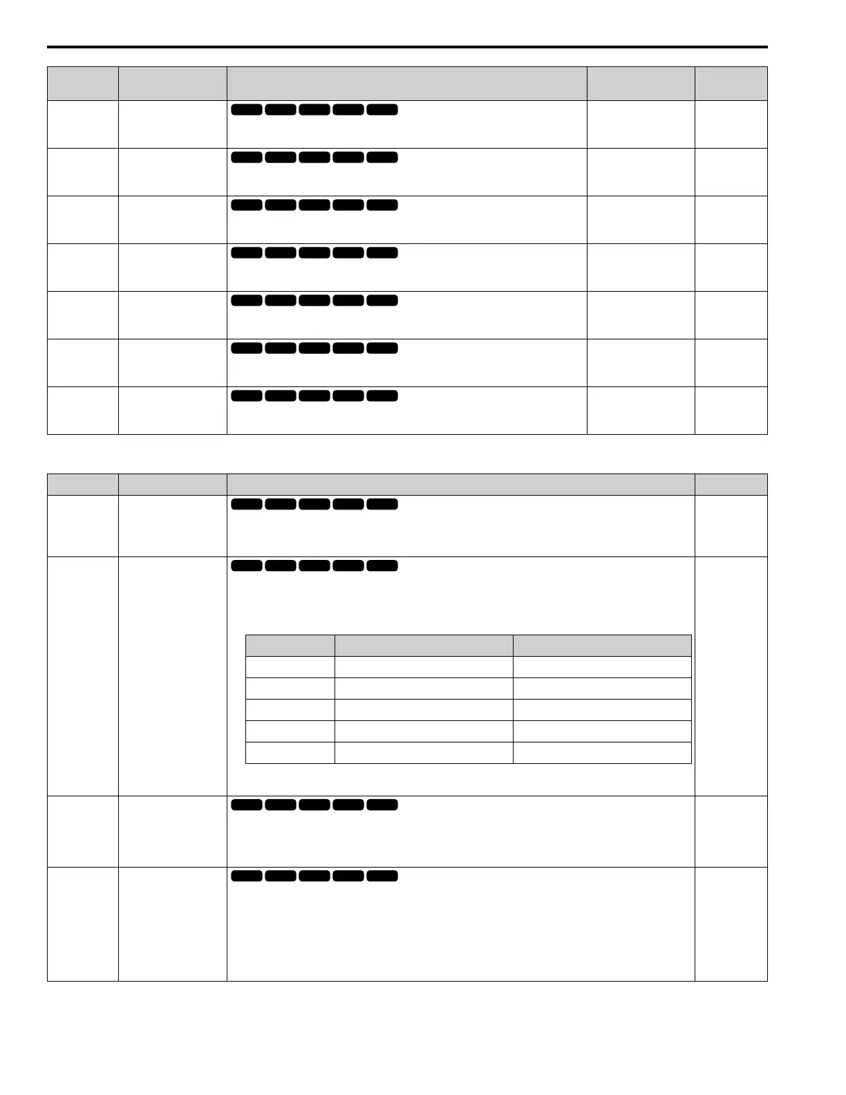
■ H2-xx: MFDO Setting Values
Setting Value Function Description Ref.
0 During Run
The terminal activates when you input a Run command and when the drive is outputting voltage.
ON : Drive is running
OFF : Drive is stopping
318
1 Zero Speed
The terminal turns on when the output frequency drops below the value of E1-09 [Minimum Output Frequency] or b2-
01 [DC Injection/Zero SpeedThreshold].
Note:
Parameter A1-02 [Control Method Selection] selects which parameter is the reference.
A1-02 Setting Control Method Selection Parameter Used as the Reference
0 V/f E1-09
2 OLV b2-01
5 OLV/PM E1-09
6 AOLV/PM E1-09
8 EZOLV E1-09
ON : Output frequency < value of E1-09 or b2-01.
OFF : Output frequency ≥ value of E1-09 or b2-01.
318
2 Speed Agree 1
The terminal activates when the output frequency is in the range of the frequency reference ± L4-02 [Speed Agree
Detection Width].
ON : The output frequency is in the range of “frequency reference ± L4-02”.
OFF : The output frequency does not align with the frequency reference although the drive is running.
319
3 User-Set Speed Agree 1
The terminal activates when the output frequency is in the range of L4-01 [Speed Agree Detection Level] ± L4-02
[Speed Agree Detection Width] and in the range of the frequency reference ± L4-02.
Note:
The detection function operates in the two motor rotation directions. The drive uses the L4-01 value as the
forward/reverse detection level.
ON : The output frequency is within the range as defined by the result of “L4-01 ± L4-02” and the range of frequency
reference ± L4-02.
OFF : The output frequency is not in the range of “L4-01 ± L4-02” nor the range of frequency reference ± L4-02.
319

 Loading...


