Troubleshooting
5
5.7 Parameter Setting Errors
YASKAWA TOEPYAIH6B01A HV600 AC Drive Narrow Bypass Installation & Startup 143
5.7 Parameter Setting Errors
Parameter setting errors occur when multiple parameter settings do not agree, or when parameter setting values are
not correct. Refer to the table in this section, examine the parameter setting that caused the error, and remove the
cause of the error. You must first correct the parameter setting errors before you can operate the drive. The drive will
not send notification signals for the faults and alarms when these parameter setting errors occur.
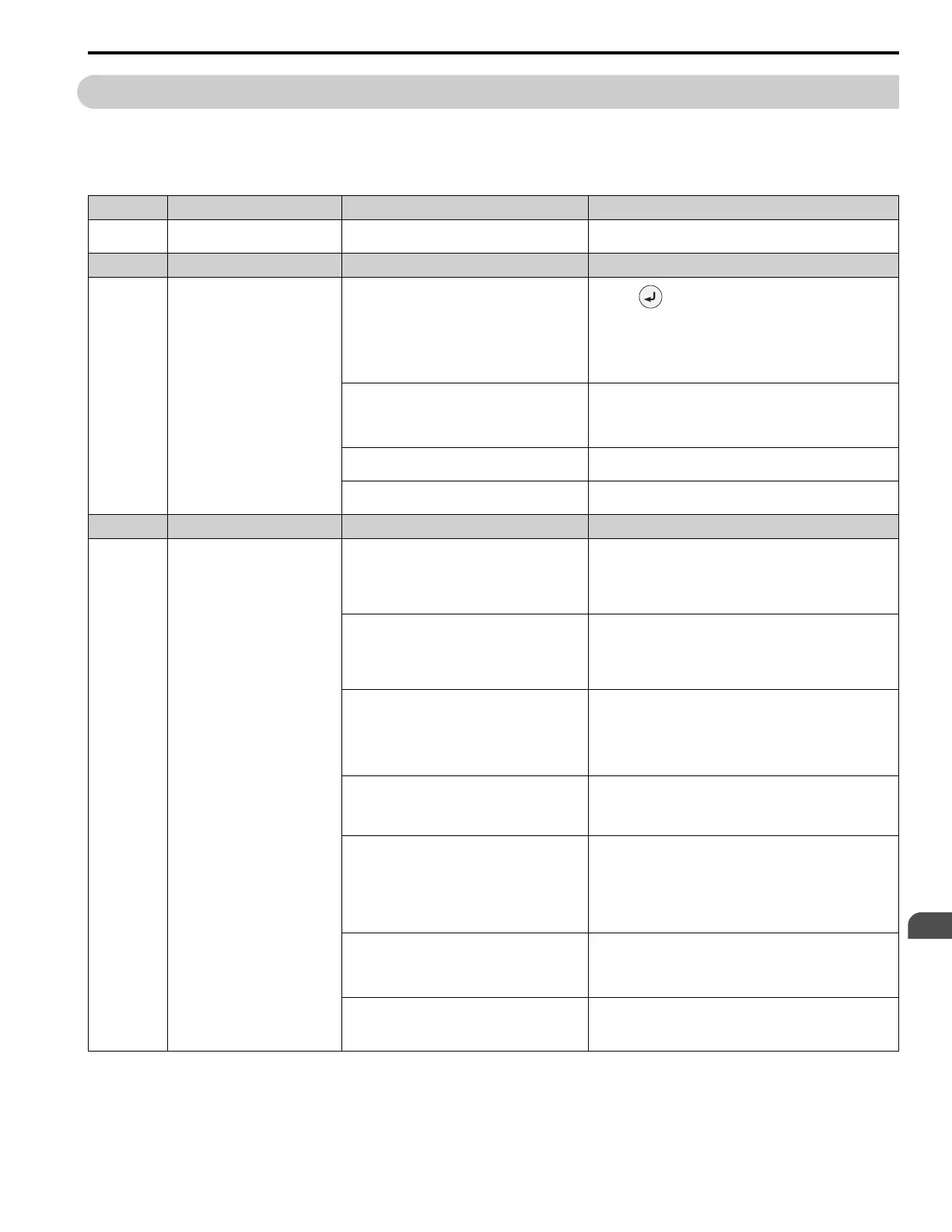
Code Name Causes Possible Solutions
oPE01 Drive Capacity Setting Error
The value set in o2-04 [Drive Model (KVA) Selection]
does not agree with the drive model.
Set o2-04 to the correct value.
Code Name Causes Possible Solutions
oPE02 Parameter Range Setting Error
Parameters settings are not in the applicable setting
range.
1. Push to show U1-18 [oPE Fault Parameter], and find
parameters that are not in the applicable setting range.
2. Correct the parameter settings.
Note:
If more than one error occurs at the same time, other oPExx
errors have priority over oPE02.
You set E2-01 ≤ E2-03 [Motor Rated Current (FLA)
≤ Motor No-Load Current].
Make sure that E2-01 > E2-03.
Note:
If it is necessary to set E2-01 < E2-03, first lower the value set
in E2-03, and then set E2-01.
You set S3-09 < S3-10 [PI2 Control Output Upper
Limit < PI2 Control Output Lower Limit].
Make sure that S3-09 > S3-10 at all times.
You set S3-13 > S3-15 [PI2 Control Low Feedback
Lvl > PI2 Control High Feedback Lvl].
Make sure that S3-13 < S3-15 at all times.
Code Name Causes Possible Solutions
oPE03 Multi-Function Input Setting Err
The settings for these parameters do not agree:
• Z2-01 to Z2-08 [Digital Input 1 Function (TB2-1)
to Digital Input 8 Function (TB2-8)]
• H1-01 to H1-07 [Terminals S1 to S7 Function
Selection]
Correct the parameter settings.
The settings for MFDIs Z2-01 to Z2-08 overlap.
Note:
This does not include H1-xx = 20 to 2F [MFDI
Function Selection = External Fault] and
[Reserved].
Set the parameters correctly to prevent MFDI function overlap.
A minimum of two of these MFDI combinations are
set to Digital Inputs (H1-xx and H7-01 to H7-04) at
the same time:
• Setting value 1E [Reference Sample Hold]
• Setting values 44 to 46 [Add Offset Frequency 1 to
3 (d7-01 to d7-03)]
Remove the function settings that are not in use.
These commands are set in Digital Inputs (H1-xx and
H7-01 to H7-04) at the same time:
• Setting values 61 [Speed Search from Fmax] and
62 [Speed Search from Fref]
Remove the function settings that are not in use.
These groups of MFDI functions are not set to Digital
Inputs (H1-xx and H7-01 to H7-04) at the same time:
• Setting values 3E [PID Setpoint Selection 1] and
3F [PID Setpoint Selection 2]
• Setting values 83 [Dedicated Multi-Setpoint YA-
02], 84 [Dedicated Multi-Setpoint YA-03], and 85
[Dedicated Multi-Setpoint YA-04]
Set the MFDI groups correctly.
Settings for N.C. and N.O. input [H1-xx] for these
functions were selected at the same time:
• Setting value 15 [Fast Stop (N.O.)]
• Setting value 17 [Fast Stop (N.C.)]
Remove one of the function settings.
These MFDI functions are set at the same time:
• H1-xx = 6A [Drive Enable]
• H1-xx = 70 [Drive Enable 2]
Remove one of the function settings.

 Loading...


