8.3 BACnet Communications
272 YASKAWA TOEPYAIH6B01A HV600 AC Drive Narrow Bypass Installation & Startup
The bypass is prepared to start communication with the controller.
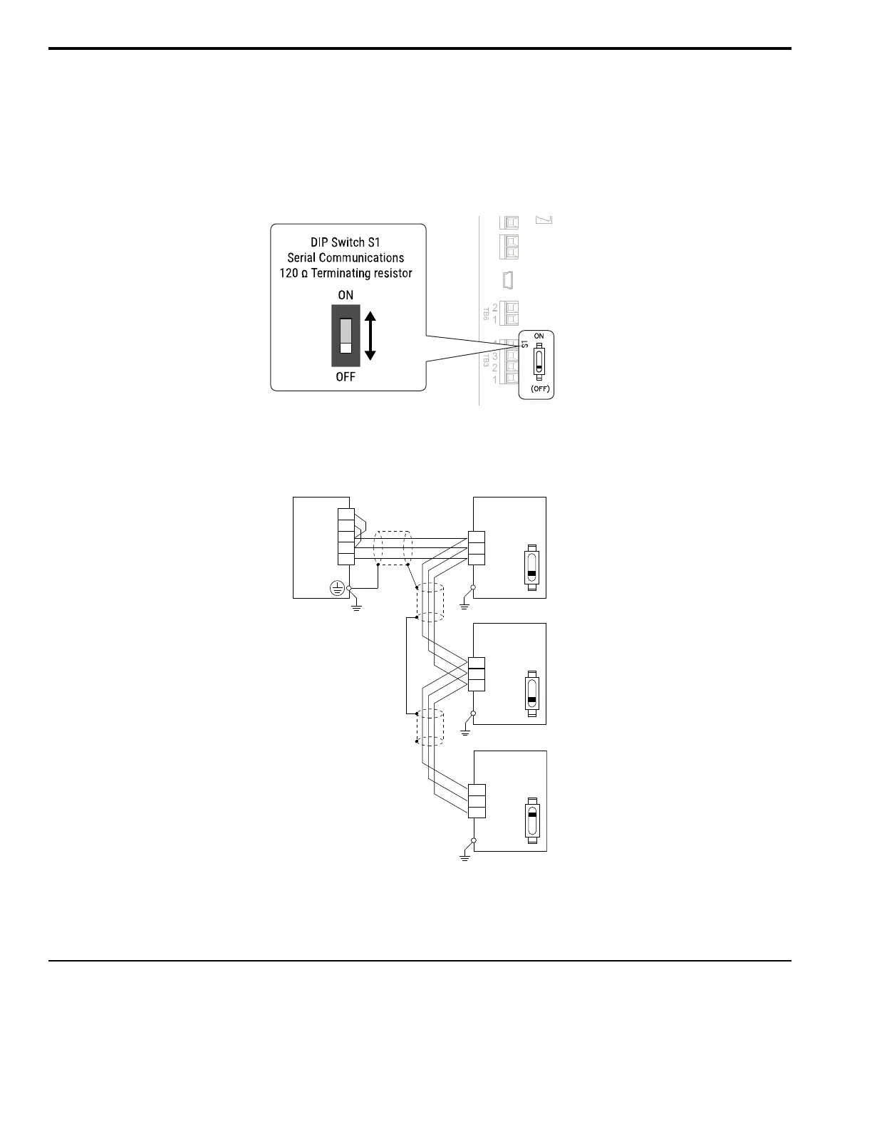
■ Set the Termination Resistor
You must enable the termination resistor on the serial terminals of the bypasses on the two physical ends of the
network to use serial communications. Use DIP switch S1 on the bypass control PCB to enable and disable the built-
in termination resistor. Refer to Figure 8.3 for an example of how to set DIP switch S1. Use the tip of a tweezers or a
small flat-blade screwdriver to set the DIP switch. When you install the bypass at the end of the network line, set DIP
switch S1 to “ON” to enable the termination resistor. Set DIP switch S1 to “OFF” on all other bypasses.
Figure 8.3 Termination Resistor DIP Switch S1
■ Wiring Diagram for More than One Bypass
Figure 8.4 shows how to wire more than one connected bypass using serial communications.
Figure 8.4 Wiring Diagram for More than One Bypass
Note:
When you install the bypass at the end of the network line, set DIP switch S1 to “ON” to enable the termination resistor. Set DIP switch S1 to
“OFF” on all other bypasses.
◆ Bypass Operations by Serial Communications
Parameters will apply to the settings when the bypass is running during serial communications. This section gives
information about the available functions and their related parameters.
PLC
R+
Bypass
OFF
R-
S+
S-
IG
2
3
1
TXRX+
TXRX-
IG5
S1
Bypass
OFF
2
3
1
TXRX+
TXRX-
IG5
S1
Bypass
ON
2
3
1
TXRX+
TXRX-
IG5
S1

 Loading...


