Electrical Installation
3
3.7 Control I/O Connections
YASKAWA TOEPYAIH6B01A HV600 AC Drive Narrow Bypass Installation & Startup 61
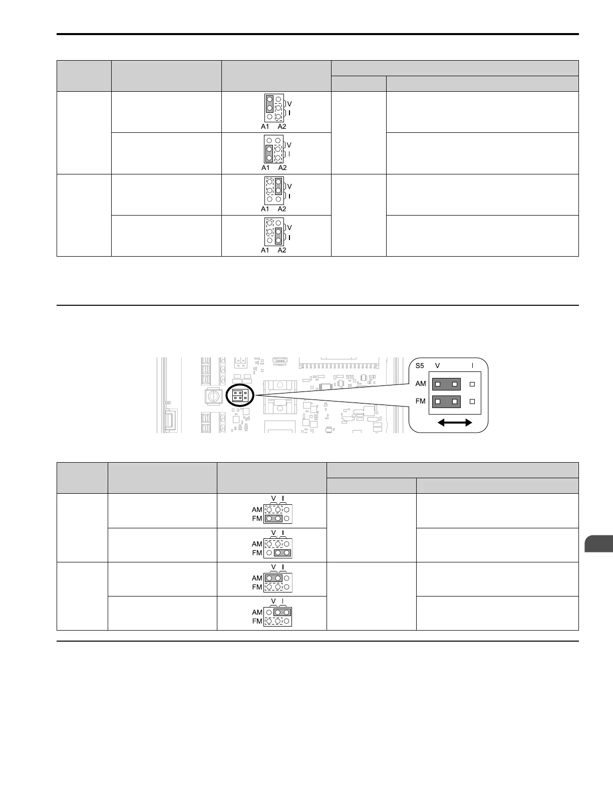
Table 3.17 MFAI Terminals A1 and A2 Signal Settings
Terminal Types of Input Signals Jumper Switch S1
Parameter
No. Signal Level
A1
Voltage input
(Default)
H3-01
0: 0 V to 10 V/0% to 100% (input impedance: 20 kΩ)
Current input
2: 4 mA to 20 mA/0% to 100% (input impedance: 250 Ω)
3: 0 mA to 20 mA/0% to 100% (input impedance: 250 Ω)
A2
Voltage input
H3-09
0: 0 V to 10 V/0% to 100% (input impedance: 20 kΩ)
Current input
(Default)
2: 4 mA to 20 mA/0% to 100% (input impedance: 250 Ω)
3: 0 mA to 20 mA/0% to 100% (input impedance: 250 Ω)
Note:
Set H3-02, H3-10 = 0 [Terminal A1 Function Selection, Terminal A2 Function Selection = Frequency Reference] to set A1 and A2 to
frequency reference. The drive will add the analog input values together to make the frequency reference.
◆ Set Output Signals for MFAO Terminals FM, AM
Set the signal type for terminals AM and FM to voltage or current output. Use jumper switch S5 and H4-07, H4-08
[Terminal FM Signal Level Select, Terminal AM Signal Level Select] to set the signal type.
Figure 3.19 Location of Jumper Switch S5
Terminal Types of Output Signals Jumper Switch S5
Parameter
No. Signal Level
FM
Voltage output
(Default)
H4-07
0: 0 V to 10 V
Current output 2: 4 mA to 20 mA
AM
Voltage output
(Default)
H4-08
0: 0 V to 10 V
Current output 2: 4 mA to 20 mA
◆ Switch ON Termination Resistor for RS-485 Communications
This switch should always be in the ON position.

 Loading...


