Electrical Installation
3
3.5 Bypass PCB Control Circuit
YASKAWA TOEPYAIH6B01A HV600 AC Drive Narrow Bypass Installation & Startup 47
3.5 Bypass PCB Control Circuit
Note:
When possible, use these control terminal connections on the Bypass PCB. There are additional control I/O terminals available on the Drive
Control PCB, however those terminals are active in Drive Mode ONLY and may not report correctly in Bypass Mode.
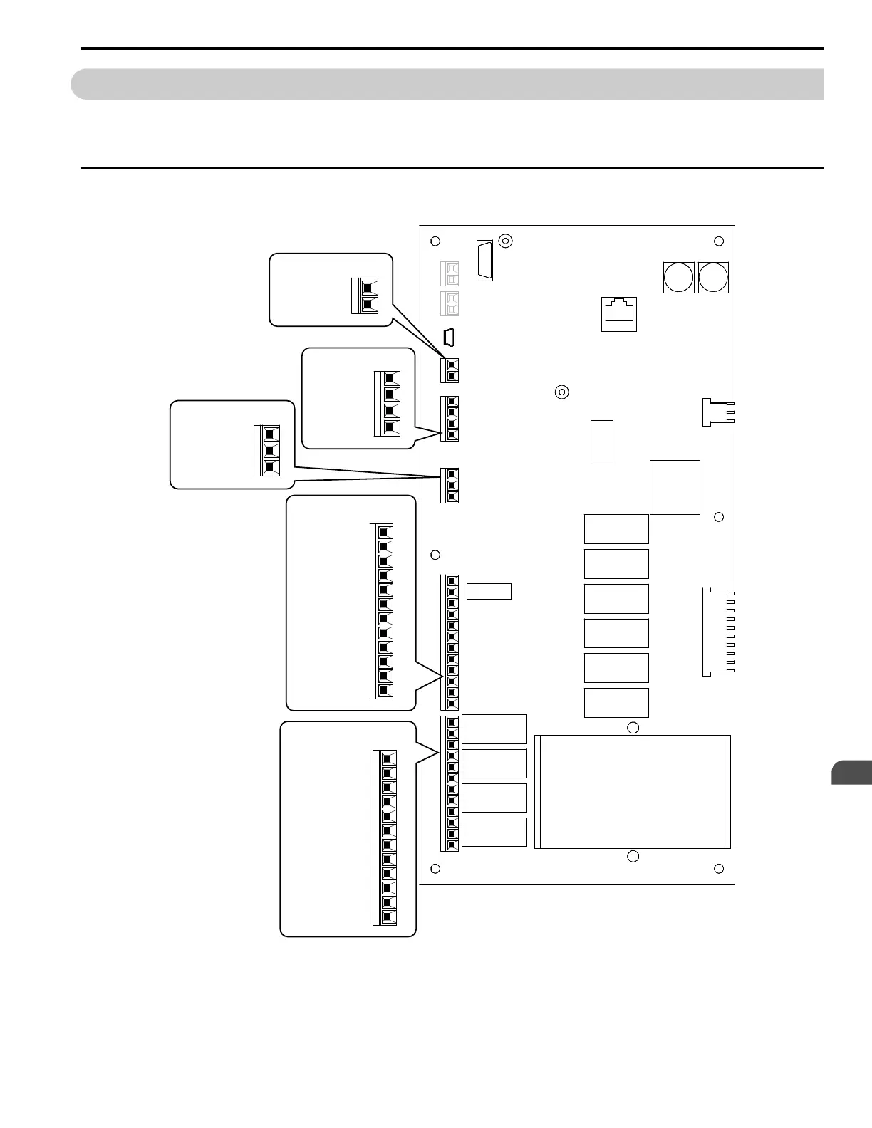
◆ Control Circuit Terminal Arrangement
The bypass control circuit terminals are in the positions shown in Figure 3.6.
Figure 3.6 Bypass Control Circuit Terminal Arrangement
TB6
2
1
2
1
4
3
TB3
2
1
3
TB4
2
1
4
3
6
5
8
7
10
9
12
11
2
1
4
3
6
5
8
7
10
9
12
11
TB2 TB1
12. SHIELD
1 1. SHIELD
10. IG24
9. IG24
8. DI-8
7. DI-7
6. DI-6
5. DI-5
4. DI-4
3. DI-3
2. DI-2
1. DI-1
TB2
TB3
4. SHIELD
3. TXRX-
2. TXRX+
1. IG5
TB1
12. DO-10 NO
1 1. DO-10 C
10. DO-10 NC
9. DO-9 NO
8. DO-9 C
7. DO-9 NC
6. DO-8 NO
5. DO-8 C
4. DO-8 NC
3. DO-7 NO
2. DO-7 C
1. DO-7 NC
TB4
3. COMMON
2. AI-1
1. +10 Vdc
TB6
2. GROUND
1. GROUND

 Loading...


