Mechanical Installation
2
2.7 Removing/Reattaching Covers
YASKAWA TOEPYAIH6B01A HV600 AC Drive Narrow Bypass Installation & Startup 31
2.7 Removing/Reattaching Covers
This section gives information about how to remove and reattach the bypass front cover and drive front cover and
terminal cover for wiring and inspection.
Refer to Table 2.1 for more information.
Table 2.1 Procedures to Remove Covers by Model
Bypass Model
H6BP
Bypass Cover Removal Procedure Drive Cover Removal Procedure
D002 - D074
B001 - B077
Procedure 1
31
Procedure A
32
◆ Removing/Reattaching the Bypass Cover Using Procedure 1
DANGER! Electrical Shock Hazard. Do not examine, connect, or disconnect wiring on an energized bypass. Before servicing,
disconnect all power to the equipment and wait for the time specified on the warning label at a minimum. The internal capacitor
stays charged after the bypass is de-energized. The charge indicator LED extinguishes when the DC bus voltage decreases below
50 Vdc. When all indicators are OFF, remove the covers before measuring for dangerous voltages to make sure that the bypass is
safe. If you do work on the bypass when it is energized, it will cause serious injury or death from electrical shock.
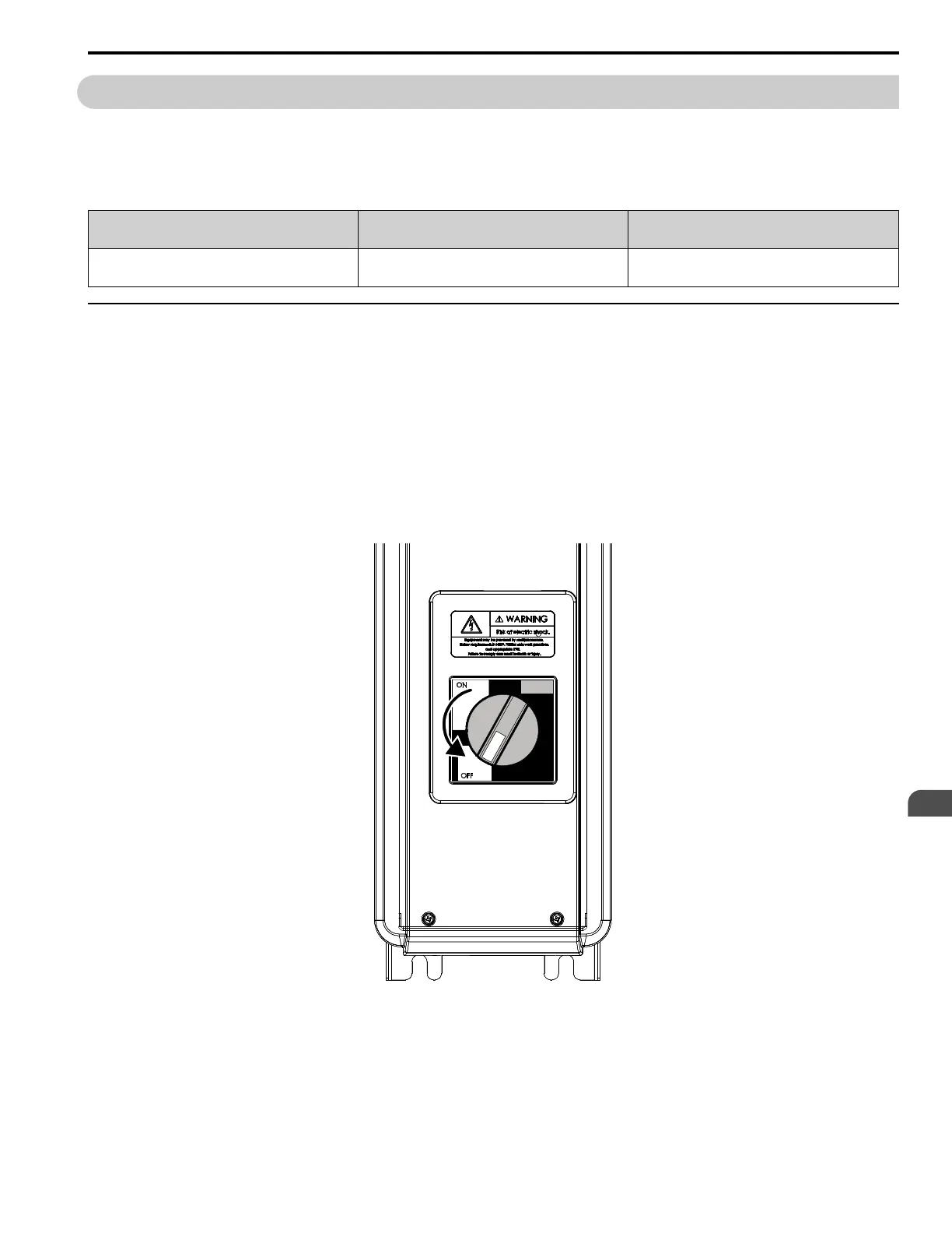
1. Turn the disconnect handle to the “OFF” position.
DANGER! Electrical Shock Hazard. Do not examine, connect, or disconnect wiring on an energized bypass. Before
servicing, disconnect all power to the equipment and wait for the time specified on the warning label at a minimum. The
internal capacitor stays charged after the bypass is de-energized. The charge indicator LED extinguishes when the DC
bus voltage decreases below 50 Vdc. When all indicators are OFF, remove the covers before measuring for dangerous
voltages to make sure that the bypass is safe. If you do work on the bypass when it is energized, it will cause serious injury
or death from electrical shock.
Figure 2.7 Disconnect Power

 Loading...


