4.3 External Dimensions
4-9
4
Specications, Ratings, and External Dimensions of SGM7E Servomotors
4.3
External Dimensions
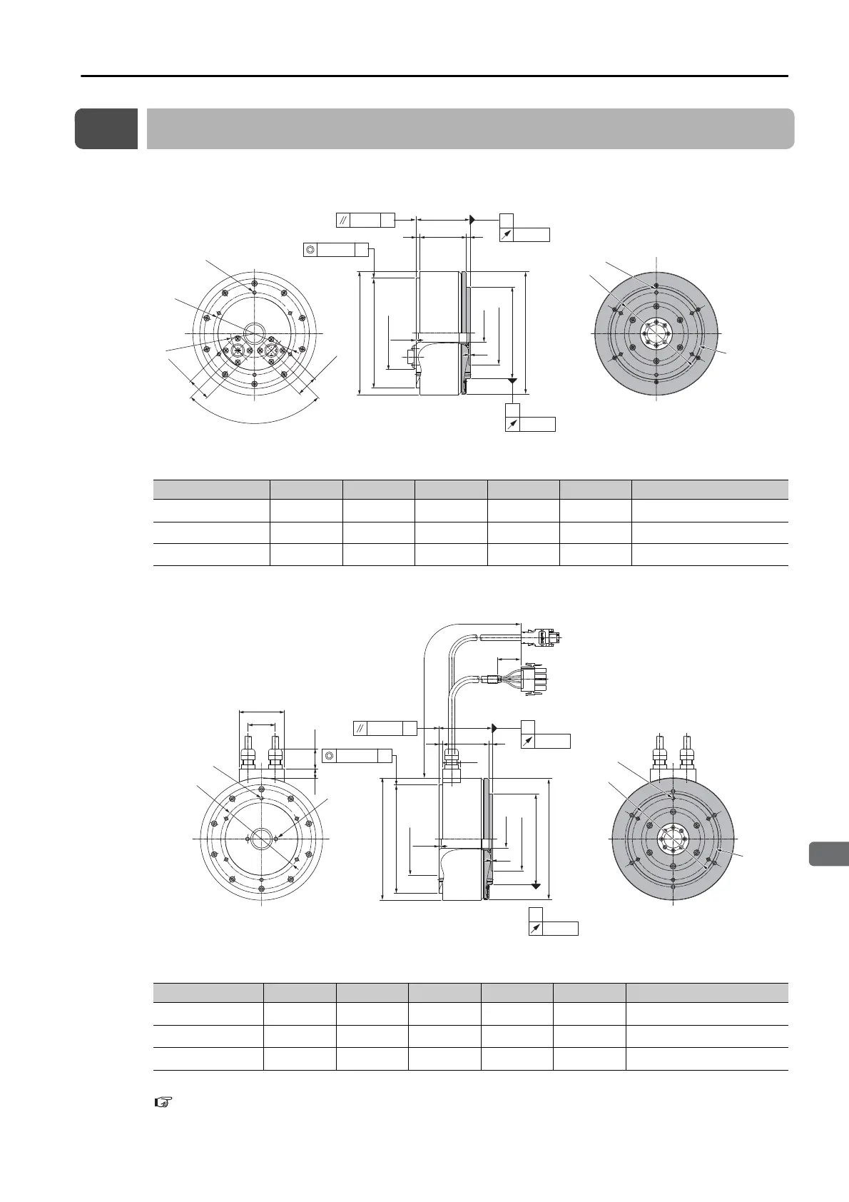
SGM7E-
B
• Flange Specification 1
* The shaded section indicates the rotating parts.
Note: Values in parentheses are reference dimensions.
• Flange Specification 4
* The shaded section indicates the rotating parts.
Note: Values in parentheses are reference dimensions.
Refer to the following section for information on connectors .
4.3.1 Connector Specifications
on page 4-13
Model SGM7E- L (LL) LB LH LA Approx. Mass [kg]
02B
A11 59 51
120 20 100
4.8
05B
A11 88 80
120 20
100
5.8
07B
A11 128 120
120
20
100
8.2
Model SGM7E- L (LL) LB LH LA Approx. Mass [kg]
02B
A41 59 51
120 20 100
4.8
05B
A41 88 80
120 20
100
5.8
07B
A41 128 120
120 20
100
8.2
(LL)
L
6
×
M4
×
8
(Divided into equal
sections at 60
°
.)
6
×
M4
×
8
(Divided into equal
sections at 60
°
.)
25.4
23.4
A
0.07 dia.
0.07 B
LB dia.
LH
dia.
LA dia.
B
0.02
0.04
A
90
dia.
4
135 dia.
(80 dia.)
(0.1)
(70 dia.)
134 dia.
90°
R26
90
dia.
4
*
Unit: mm
(1)
300±50
(35)
10
(22)
90
dia.
4
20
30
50
135
dia.
(80
dia.
)
(70
dia.
)
LA
dia.
134
dia.
(LL)
L
(1)
4
A
0.07 dia.
0.07 B
LB
dia.
LH
dia.
B
0.02
0.04
A
90
dia.
*
(0.1)
Unit: mm
6
×
M4
×
8
(Divided into equal
sections at 60
°
.)
6
×
M4
×
8
(Divided into
equal sections
at 60
°
.)
(2
×
M4
×
8)
(For use by
Yaskawa)