4-12
Precautions for Rotational and Stationary Autotuning
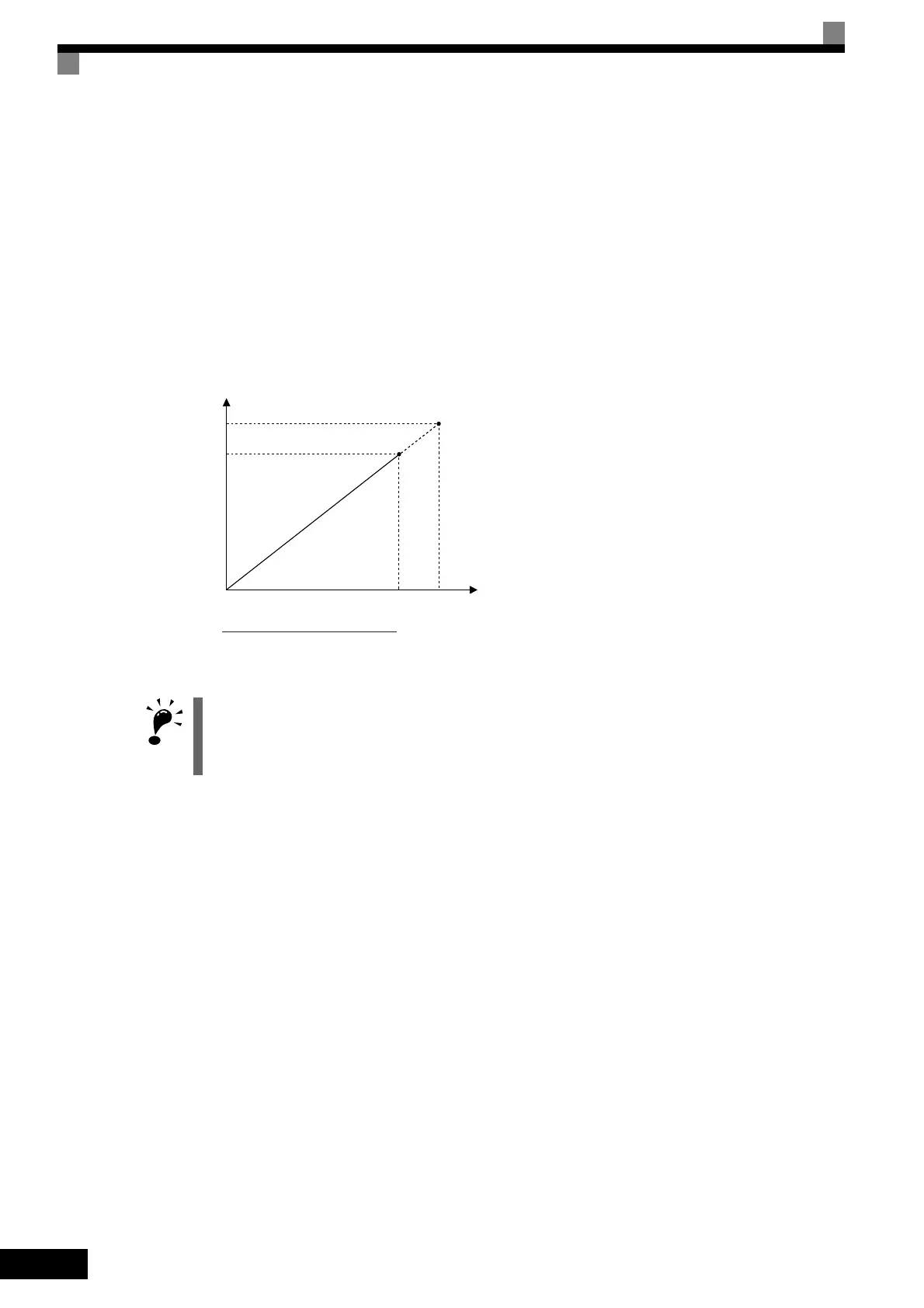
Lower the base voltage based on Fig 4.4 to prevent saturation of the Inverter’s output voltage when the rated
voltage of the motor is higher than the voltage of the power supply to the Inverter. Use the following proce-
dure to perform autotuning.
1. Input the voltage of the input power supply to T1-03 (Motor rated voltage).
2. Input the results of the following formula to T1-05 (Motor base frequency):
(Base frequency from the motor’s nameplate × setting of T1-03)/(Rated voltage from motor’s nameplate)
3. Perform autotuning.
After having completed autotuning, set E1-04 (Max. output frequency) to the base frequency shown on the
motor nameplate.
Fig 4.4 Motor Base Frequency and Inverter Input Voltage Setting
Precautions After Using Rotational and Stationary Autotuning
• After completing autotuning, set E1-04 (Max. output frequency) to the base frequency from the motor’s
nameplate.
• In stationary autotuning 1, when the motor is first operated in the drive mode after tuning, the remaining
motor constants E2-02 (Motor rated slip) and E2-03 (Motor no-load current) are set automatically. To per-
form an operation immediately after stationary autotuning 1, use the following procedure under the recom-
mended conditions.
1. Check the values of E2-02 and E2-03 in verify mode or advanced programming mode.
2. Run the motor once in drive mode under the following conditions.
• The Inverter and the motor are connected.
• The motor shaft is not locked with a mechanical brake or other stopping mechanism (or function).
• A motor-load ratio of 30% or less is maintained.
• A speed of 30% or more of the base frequency set at E1-06 (default = highest frequency) is maintained
at a constant speed for one second or more.
3. After stopping the motor, check the values of E2-02 and E2-03 again in verify mode or advanced program-
ming mode. If the values of E2-02 and E2-03 differ from the ones before the first operation was carried
out, the settings have been successfully completed. Next, check if the values are suitable or not.
1. When speed precision is required at high speeds (i.e., 90% of the rated speed or higher), set T1-03 (Motor
rated voltage) to the input power supply voltage × 0.9.
2. When operating at high speeds (i.e., 90% of the rated speed or higher), the output current will increase as
the input power supply voltage is reduced. Be sure to provide sufficient margin in the Inverter current.
Output voltage
Output frequency
Rated voltage from
motor nameplate
T1-03
0
Rated voltage from motor nameplate
Base frequency
from motor nameplate
×T1-03
Base frequency
from motor nameplate
 Loading...


