10-22
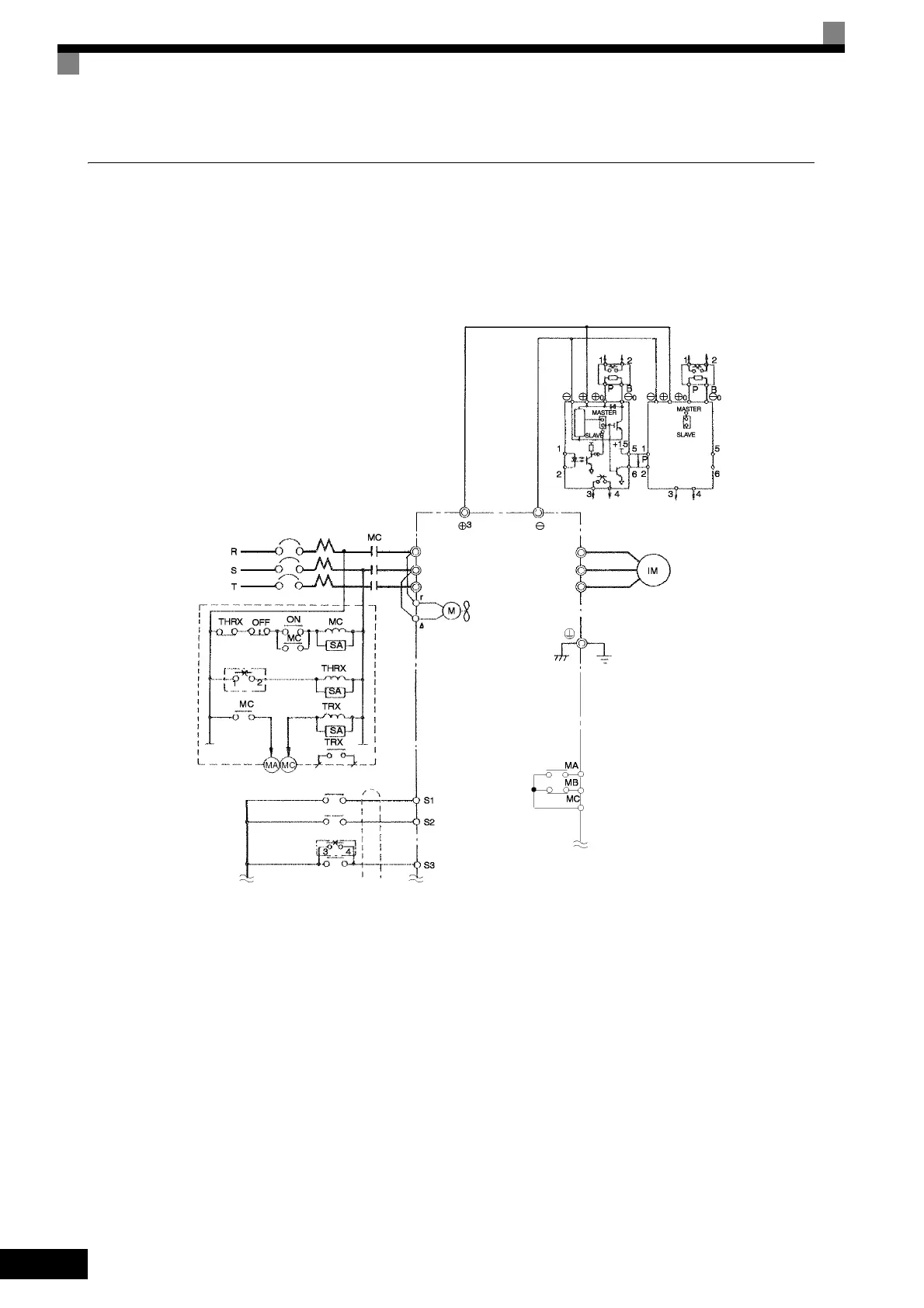
Using Braking Units in Parallel
This example shows wiring for using two Braking Units in parallel.
There are connectors for selecting whether each Braking Unit is to be a Master or Slave. Select “Master” for
the first Braking Unit only, and select “Slave” for all other Braking Units (i.e., from the second Unit onwards).
Fig 10.11
A sequence is required to turn OFF the
power supply for the thermal overload relay
trip contacts of the Braking Resistor Unit.
MCCB
Inverter
Motor
Ground to 100 Ω max.
Forward Run Com-
mand (forward run
when ON)
Reverse Run Com-
mand (reverse run
when ON)
Forward Run/Stop
Reverse Run/Stop
Braking Unit
External fault
Fault contacts
3-phase power
200 to 220 V 50 Hz
200 to 230 V 60 Hz
Thermal
protector
Thermal
protector
Brak-
ing
Resis-
tor Unit
Brak-
ing
Resis-
tor Unit
Thermal switch
Level
detector
Braking Unit 2
Thermal switch
Cooling fan
Overload relay trip contact
of Braking Resistor Unit
Fault contact output
* Disable stall prevention during deceleration by setting L3-04 to Resistor Unit. The motor may
not stop within the deceleration time if this setting is not changed.
R/L1
S/L2
T/L3
U/T1
V/T2
W/T3
 Loading...


