Input Terminal Functions
6-85
Stopping the Inverter by Notifying Programming Device Errors to the
Inverter (External Fault Function)
The external fault function performs the error contact output, and stops the Inverter operation if the Inverter
peripheral devices break down or an error occurs. The digital operator will display EFx (External fault [input
terminal Sx]). The x in EFx shows the terminal number of the terminal that input the external fault signal. For
example, if an external fault signal is input to terminal S3, EF3 will be displayed.
To use the external fault function, set one of the values 20 to 2F in one of the constants H1-01 to H1-10 (multi-
function contact input terminal S3 to S12 function selection).
Select the value to be set in H1-01 to H1-10 from a combination of any of the following three conditions.
• Signal input level from peripheral devices
• External fault detection method
• Operation during external fault detection
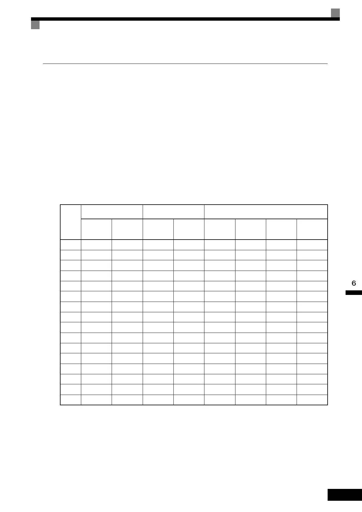
The following table shows the relationship between the combinations of conditions and the set value in H1-
.
Note 1. Set the input level to detect errors using either signal ON or signal OFF. (NO contact: External fault when ON; NC contact: External fault when
OFF).
2. Set the detection method to detect errors using either constant detection or detection during operation.
Constant detection: Detects while power is supplied to the Inverter.
Detection during operation: Detects only during Inverter operation.
Set
Value
Input Level
(See Note 1.)
Error Detection Method
(See Note 2.)
Operation During Error Detection
NO Con-
tact
NC Con-
tact
Constant
Detection
Detection
During
Operation
Deceler-
ate to Stop
(Error)
Coast to
Stop
(Error)
Emer-
gency Stop
(Error)
Continue
Operation
(Warning)
20 Yes Yes Yes
21 Yes Ye s Yes
22 Yes Yes Ye s
23 Yes Ye s Ye s
24 Yes Yes Ye s
25 Yes Ye s Ye s
26 Yes Yes Ye s
27 Yes Ye s Yes
28 Yes Yes Yes
29 Yes Ye s Yes
2A Yes Yes Yes
2B Yes Ye s Yes
2C Ye s Yes Yes
2D Yes Yes Yes
2E Ye s Ye s Yes
2F Yes Ye s Yes
 Loading...


