6-136
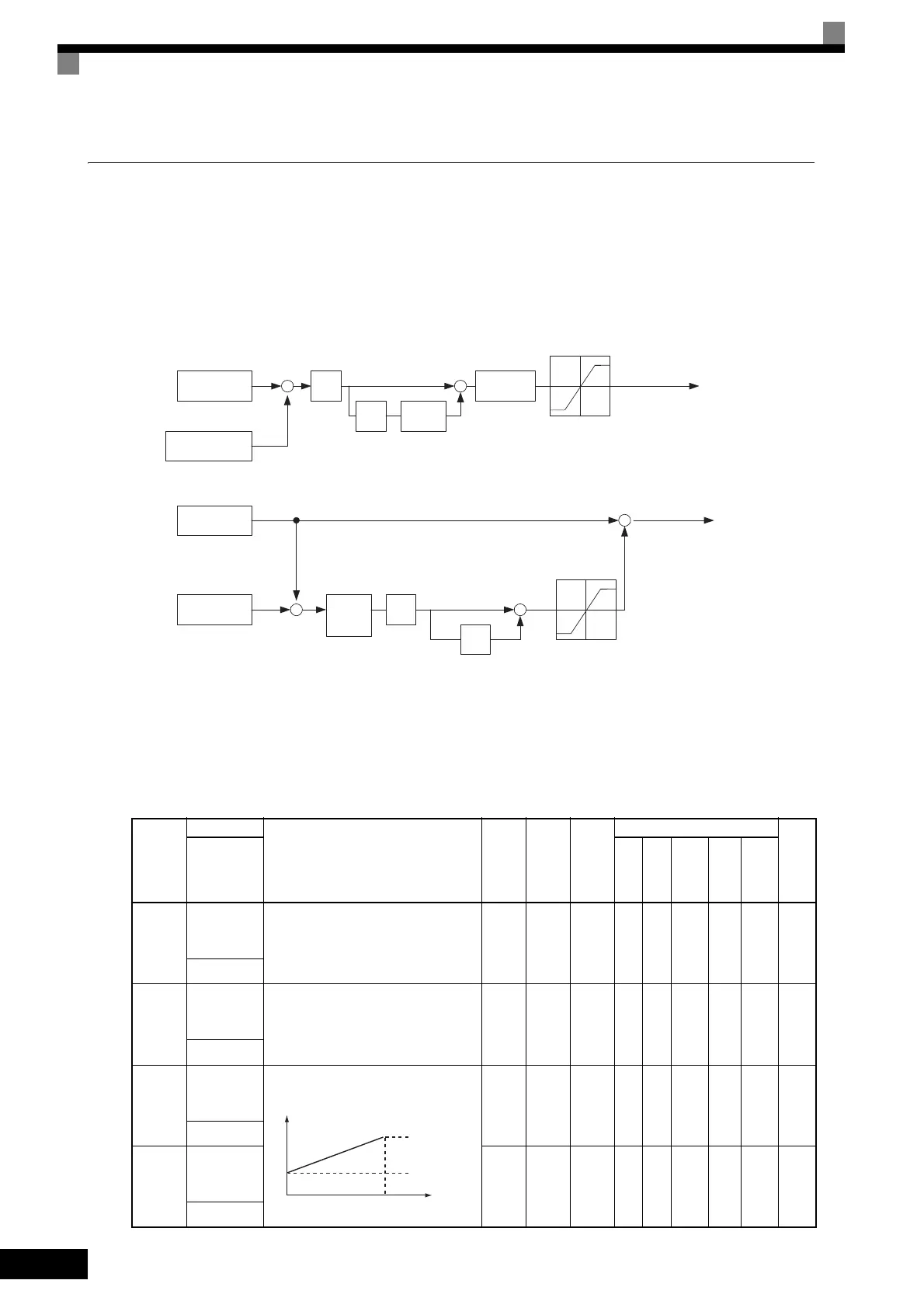
Speed Control (ASR) Structure
Speed control (ASR) during vector control adjusts the torque reference so that the deviation between the
speed reference and the estimated speed (PG feedback or speed estimator) is 0. Speed control (ASR) during V/
f control with a PG adjusts the output frequency so that the deviation between the speed reference and the esti-
mated speed (PG feedback or speed estimator) is 0. The following block diagram shows the structure of the
speed control for vector or V/f control with a PG.
Fig 6.71 Speed Control Block Diagrams
Related Constants
Con-
stant
Number
Name
Description
Setting
Range
Factory
Setting
Change
during
Opera-
tion
Control Methods
MEMO
BUS
Reg-
ister
Display
V/f
V/f
with
PG
Open
Loop
Vec-
tor
1
Flux
Vec-
tor
Open
Loop
Vec-
tor
2
C5-01
ASR propor-
tional (P)
gain 1
Sets the proportional gain of the speed
loop (ASR.)
0.00 to
300.00
*2
20.00
*1
Yes N o A No A A
21BH
比例增益 1
C5-02
ASR inte-
gral (I) time
1
Sets the integral time of the speed loop
(ASR) in 1-second units.
0.000
to
10.000
0.500
s
*1
Yes N o A No A A
21CH
积分时间 1
C5-03
ASR propor-
tional (P)
gain 2
Usually setting is not necessary.
Set to change the rotational speed gain.
0.00 to
300.00
*2
20.00
*1
Yes N o A No A A
21DH
比例增益 2
C5-04
ASR inte-
gral (I) time
2
0.000
to
10.000
0.500
s
*1
Yes N o A No A A
21EH
积分时间 2
Frequency
reference
Detected speed
Estimated speed
P
I
To r que limits
To r que reference
+
+
+
−
Speed Control Block Diagram for Vector Control
Frequency
reference
Detected speed
P
I
Change
rate
limiter
Limit
+
+
+
−
Speed Control Block Diagram for V/f Control with a PG
+
+
Output frequency
C5-01, C5-03
C5-02, C5-04
C5-06
I
limit
C5-08
Primary
filter
L7-01 to L7-04
C5-01
C5-03
C5-02, C5-04
C5-05
(C5-10)
P, I
0 E1-04 Motor speed (Hz)
P=C5-01
I=C5-02
P=C5-03
I=C5-04
 Loading...


