6-48
Setting Torque Limits Using Constants and an Analog Input
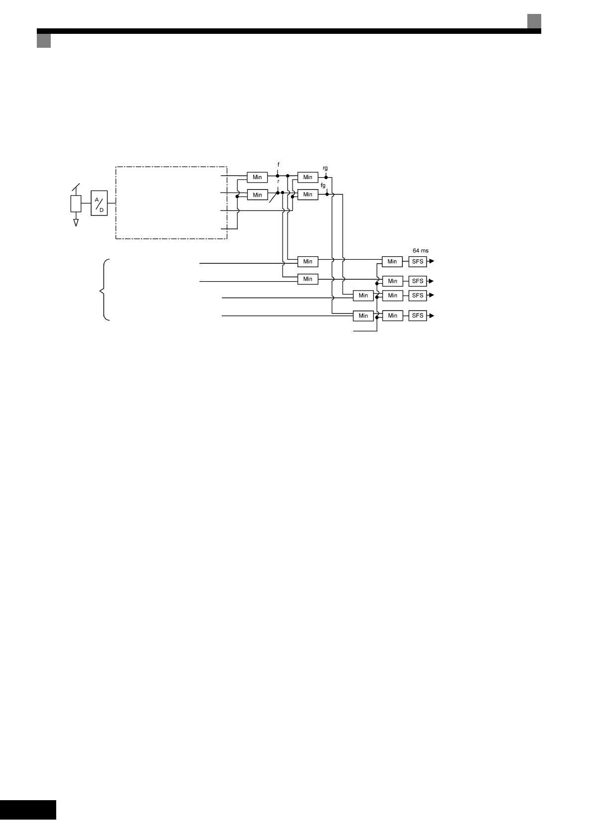
The following block diagram shows the relationship between torque limit using constants and torque limit
using an analog input.
Fig 6.38 Torque Limit Using Constants and an Analog Input
Selecting the Control Method for Torque Limit during Acceleration and Deceleration
L7-07 is used to select the control method for the torque limit during acceleration and deceleration. The selec-
tions are proportional control and integral control. For applications, such as presses, in which the torque limit
will be reached during acceleration and deceleration, torque control can be given priority by selecting integral
control. To increase the change in frequency for the torque limit when integral control is selected, decrease the
value set for L7-06 (Integral Time Setting for Torque Limit).
Setting Precautions
• When the torque limit function is operating, control and compensation of the motor speed is disabled
because torque control is given priority. Therefore, the acceleration and deceleration times may increase or
the number of motor rotations may decrease.
• When using the torque limit to raise and lower loads, do not carelessly lower the torque limit value, as this
may result in the motor falling or slipping.
• Torque limits using an analog input are the upper limit value (during 10 V or 20 mA input) of 100% of the
motor rated torque. To make the torque limit value during 10 V or 20 mA input 150% of the rated torque,
set the input terminal gain to 150.0 (%). Adjust the gain for multi-function analog input terminal A2 using
H3-10 and for multi-function analog input terminal A3 using H3-06.
• The torque limit accuracy is ±5% at the output frequency of 10 Hz or above. When output frequency is less
than 10 Hz, accuracy is lowered.
• When the torque is limited while L7-07 is set to 1 (integral control), the acceleration and deceleration
times may increase or the motor speed may not agree with the speed reference value.
Multi-function analog input
Terminal
A2 or A3
Forward torque limit
(set value = 10)
Negative torque limit
(set value = 11)
Regenerative torque limit
(set value = 12)
Positive/negative torque limit
(set value = 15)
Positive forward drive
torque
Reverse positive regenerative torque
Forward negative regenerative torque
Reverse
drive
reverse
torque
Min: Minimum value priority circuit
Constants
Forward torque limit
(L7-01)
Reverse torque limit
(L7-02)
Forward regenerative torque
limit (L7-03)
Reverse regenerative torque
limit (L7-04)
175% of Inverter rated current
Forward torque limit
Reverse torque limit
Forward regenerative
torque limit
Reverse regenerative
torque limit
 Loading...


