EasyManua.ls Logo

YASKAWA varispeed G7 CIMR-G7B series User Manual

YASKAWA varispeed G7 CIMR-G7B series
495 pages
To Next Page IconTo Next Page
To Previous Page IconTo Previous Page
Page #258 background imageLoading...
Page #258 background image
6-52
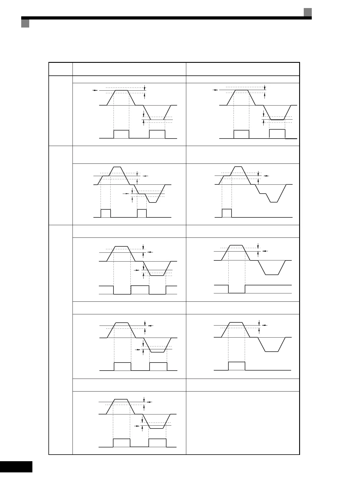
Timing Chart for Frequency Detection Operation
Related
constant
L4-01: Speed Agree Level
L4-02: Speed Agree Width
L4-03: Speed Agree Level +/
L4-04: Speed Agree Width +/
Fref/Fout
Agree
Fref/Fout Agree 1 Fref/Fout Agree 2
Fref/Set
Agree
Fref/Set Agree 1
(ON at the following conditions during frequency
agree)
Fref/Set Agree 2 +/
(ON at the following conditions during frequency
agree)
Fre-
quency
Detection
Frequency (FOUT) Detection 1
(L4-01 > | Output frequency |)
Frequency (FOUT) Detection 3
(L4-03 > Output frequency)
Frequency (FOUT) Detection 2
(L4-01 < | Output frequency |)
Frequency (FOUT) Detection 4
(L4-01 < Output frequency)
Frequency (FOUT) Detection 5
(L4-01 < | Output frequency |)
L4-02
OFF ON
Frequency
reference
L4-02
Output frequency
or motor speed
Fref/Fout Agree 1
(Multi-function output setting = 2)
OFF ON
Frequency
reference
Output frequency
or motor speed
Fref/Fout Agree 2
L4-04
(Multi-function output setting = 13)
OFF ON
tput frequency
motor speed
f/Set Agree 1
L4-02
L4-01
L4-01
L4-02
(Multi-function output setting = 3)
OFF ON
Output frequency
or motor speed
Fref/Set Agree 2
L4-04
L4-03
(Multi-function output setting = 14)
Freq. Detection 1
OFFON
Output frequency
or motor speed
L4-02
L4-02
L4-01
L4-01
(Multi-function output setting = 4)
Freq. Detection 3
OFFON
Output frequency
or motor speed
L4-04
L4-03
(Multi-function output setting = 15)
Freq. Detection 2
OFF ON
Output frequency
or motor speed
L4-02
L4-02
L4-01
L4-01
(Multi-function output setting = 5)
Freq. Detection 4
OFF ON
Output frequency
or motor speed
L4-04
L4-03
(Multi-function output setting = 16)
Freq. Detection 5
OFF ON
Output frequency
or motor speed
L4-02
L4-02
L4-01
L4-01
(Multi-function output setting = 36) OFF during baseblock

Table of Contents

Question and Answer IconNeed help?

Do you have a question about the YASKAWA varispeed G7 CIMR-G7B series and is the answer not in the manual?

YASKAWA varispeed G7 CIMR-G7B series Specifications

General IconGeneral
TypeInverter
ModelCIMR-G7B series
Power Range0.4 kW to 630 kW
Overload Capacity150% for 60 seconds
DimensionsVaries by model
Frequency Range0.1 to 400 Hz
Control MethodV/f control
Communication ProtocolsModbus RTU, DeviceNet, Profibus DP
Protection FeaturesOvervoltage, undervoltage, overload, overcurrent, short circuit
Cooling MethodForced air cooling
Ambient Temperature-10°C to +40°C
Storage Temperature-20°C to +65°C
Humidity95% RH or less (non-condensing)
AltitudeUp to 1000m without derating
Enclosure RatingIP20
Input Voltage3-Phase 200-240VAC, 380-480VAC, 500-600VAC (depending on model)

Summary

Handling Inverters

Varispeed G7 Introduction

Provides an overview of the Varispeed G7 series, including voltage classes and model variations.

Confirmations upon Delivery

Details the necessary checks to perform immediately after receiving the inverter to ensure correct model and condition.

Exterior and Mounting Dimensions

Presents detailed diagrams and dimensions for both open chassis and enclosed wall-mounted inverter types.

Checking and Controlling the Installation Site

Outlines the environmental conditions and pollution level requirements for a suitable installation site.

Installation Orientation and Space

Specifies the correct vertical installation orientation and required clearance for proper heat dissipation.

Removing and Attaching the Terminal Cover

Provides step-by-step instructions for safely removing and reattaching the terminal cover for wiring access.

Removing/Attaching the Digital Operator and Front Cover

Explains the procedure for detaching and reattaching the digital operator and front cover for accessing internal components.

Removing and Attaching the Protection Cover

Details the steps for removing and reattaching the top and bottom protection covers, especially for panel installations.

Wiring

Connections to Peripheral Devices

Illustrates typical connections between the inverter and peripheral devices like power supply, reactors, and motors.

Connection Diagram

Provides a comprehensive wiring diagram showing main circuit and control circuit connections for the inverter.

Terminal Block Configuration

Shows the physical layout and arrangement of terminal blocks for main and control circuits on the inverter.

Wiring Main Circuit Terminals

Details applicable wire sizes, connectors, and tightening torques for main circuit wiring.

Wiring Control Circuit Terminals

Covers wire sizes, closed-loop connectors, and terminal functions for control circuit wiring.

Wiring Check

Lists essential checks to perform after wiring is completed to ensure correctness and safety.

Installing and Wiring Option Boards

Explains how to install and wire various option boards, such as communication or PG boards.

Digital Operator and Modes

Digital Operator

Describes the components, displays, and keys of the digital operator, including mode indicators and functions.

Modes

Explains the different operating modes of the inverter (Drive, Quick Programming, Advanced Programming, Verify, Autotuning).

Switching Modes

Illustrates the process of navigating between different operating modes using the MENU and DATA/ENTER keys.

Drive Mode

Details the operations possible within the Drive mode, including frequency setting and parameter adjustment.

Quick Programming Mode

Explains how to monitor and set minimum user constants required for inverter trial operation.

Advanced Programming Mode

Describes how to monitor and set all inverter constants in this mode.

Verify Mode

Used to display and set user constants that have been changed from their default factory settings.

Autotuning Mode

Explains how to automatically tune and set required motor constants before operating in vector control methods.

External Fault Setting Procedure

Illustrates how to set up external fault functions for multi-function contact inputs in advanced programming mode.

Trial Operation

Overview of Trial Operation Procedure

Presents a flowchart outlining the steps for performing trial operation of the inverter.

Trial Operation Procedures

Details the step-by-step procedure for conducting the trial operation, including power supply settings and initial checks.

Basic Settings

Lists essential user constants that must be set before proceeding with trial operation.

Settings for the Control Methods

Explains how to set parameters based on the chosen control method (V/f, Vector, etc.) for autotuning.

Precautions Before Using Autotuning

Provides critical safety and operational precautions to observe before performing the autotuning process.

Constant Settings Before Autotuning

Lists the necessary user constants that need to be configured before starting the autotuning process.

Precautions for Precision Settings

Offers guidance on settings for autotuning when using motor test reports or design data.

Adjustment Suggestions

Provides guidance on adjusting specific user constants to resolve issues like hunting or vibration.

Procedure for Increasing the Speed Response

Details how to adjust parameters to improve the speed response of the control system.

User Constants

User Constant Descriptions

Explains the structure and components of the user constant tables, using b1-01 as an example.

Digital Operation Display Functions and Levels

Shows the hierarchy of the digital operator displays, listing functions and their corresponding pages.

User Constants Settable in Quick Programming Mode

Lists the minimum user constants that can be monitored and set in quick programming mode.

User Constants Settable in Advanced Programming Mode

Details the user constants that can be monitored and set in advanced programming mode.

User Constants Settable in Verify Mode

Used to display and set user constants that have been changed from their default factory settings.

User Constants for Autotuning

Details the constants that must be set before performing autotuning.

User Constants for Acceleration/Deceleration: C1

Details constants for acceleration and deceleration times, including their setting ranges and factory defaults.

User Constants for S-curve Acceleration/Deceleration: C2

Provides details on constants used for S-curve characteristics to ensure smooth acceleration and deceleration.

User Constants for Motor Slip Compensation: C3

Explains constants for slip compensation to improve speed accuracy, including gain, delay time, and limit.

User Constants for Torque Compensation: C4

Covers constants for torque compensation to increase output torque when motor load increases.

User Constants for Speed Control (ASR): C5

Lists constants for speed control, including proportional gain, integral time, and switching frequency.

User Constants for Carrier Frequency: C6

Explains constants for carrier frequency selection, including upper/lower limits and proportional gain.

User Constants for Reference: d1

Lists constants for frequency references, including preset values for multi-step speed operation.

User Constants for Reference Limits: d2

Details constants for setting output frequency upper and lower limits, and master speed reference lower limit.

User Constants for Jump Frequencies: d3

Lists constants for setting jump frequencies to avoid resonance and create a frequency reference dead band.

User Constants for Reference Frequency Hold: d4

Explains constants for holding the frequency reference, allowing it to be stored even after power loss.

User Constants for Torque Control: d5

Covers constants for torque control selection, reference delay time, and speed limits.

User Constants for Field Weakening: d6

Explains constants for field weakening, including output voltage and excitation current limit.

User Constants for V/f Pattern: E1

Lists constants for setting V/f characteristics, including input voltage and frequency settings.

Motor Setup: E2

Details constants for motor parameters like rated current, slip, no-load current, and poles.

Motor 2 Setup: E4

Explains constants for setting parameters for a second motor, including rated current, slip, and no-load current.

PG Option Setup: F1

Lists constants related to PG (pulse generator/encoder) setup, including pulse count and rotation direction.

Analog Reference Board: F2

Describes functions and settings for analog reference boards, including input signal ranges and resolution.

Digital Reference Board: F3

Details constants for setting digital reference board input methods, such as BCD or binary input.

Analog Monitor Boards: F4

Explains constants for setting channel monitor selection, gain, and bias for analog monitor outputs.

Digital Output Boards (DO-02C and DO-08): F5

Lists constants for configuring digital output boards, including channel selection and output modes.

Communications Option Boards: F6

Covers constants for communication options, including stopping methods and error detection.

Multi-function Contact Inputs: H1

Details constants for configuring multi-function contact inputs, specifying their functions and signal levels.

Multi-function Contact Outputs: H2

Explains constants for multi-function contact outputs, specifying functions and control methods.

Multi-function Analog Inputs: H3

Lists constants for multi-function analog inputs, including signal level, gain, and bias settings.

MEMOBUS Communications: H5

Covers constants for MEMOBUS communications, including slave address, baud rate, parity, and error detection.

Pulse Train I/O: H6

Details constants for pulse train inputs and outputs, including function selection, scaling, and gain.

Motor Overload: L1

Explains constants for motor overload protection, including selection, time constant, and alarm operation.

Power Loss Ridethrough: L2

Covers constants for momentary power loss detection and ridethrough time, and minimum baseblock time.

Stall Prevention: L3

Details constants for stall prevention during acceleration, running, and deceleration.

Reference Detection: L4

Explains constants for speed agreement and frequency detection levels and widths.

Fault Restart: L5

Lists constants for configuring the auto restart function after a fault occurs.

Torque Detection: L6

Covers constants for overtorque and undertorque detection, including selection, level, and time.

Torque Limits: L7

Details constants for limiting forward, reverse, regenerative, and overall torque.

Hardware Protection: L8

Explains constants for protecting the inverter from overheating, input/output open-phase faults, and other hardware issues.

Hunting Prevention Function: N1

Lists constants for the hunting prevention function, including selection, gain, and time constant.

Speed Feedback Protection Control Functions: N2

Covers constants for speed feedback protection, including gain and time constants for AFR.

High-slip Braking: N3

Details constants related to high-slip braking, such as deceleration frequency width and current limit.

Speed Estimation: N4

Explains constants for speed estimation, including integral time, proportional gain, and switching frequency.

Feed Forward: N5

Lists constants for feed forward control, including selection, motor acceleration time, and proportional gain.

Constant Settings by Function

Frequency Reference

Explains how to input the frequency reference using various sources like the digital operator or analog signals.

Run Command

Details the input methods for the Run Command, including digital operator and control circuit terminals.

Stopping Methods

Explains the four methods for stopping the inverter: deceleration, coast, DC braking, and coast with timer.

Acceleration and Deceleration Characteristics

Describes how to set acceleration and deceleration times, including S-curve characteristics and switching.

Adjusting Frequency References

Explains methods for adjusting frequency references, including analog inputs and pulse train signals.

Speed Limit (Frequency Reference Limit Function)

Details how to limit the motor speed by setting maximum and minimum output frequency references.

Improved Operating Efficiency

Explains functions for improving motor operating efficiency, such as slip compensation.

Machine Protection

Explains functions for protecting the machine, including reducing noise and stall prevention.

Continuing Operation

Describes functions for continuing or automatically restarting inverter operation after errors.

Inverter Protection

Explains functions for protecting the inverter and its braking resistor from overheating.

Input Terminal Functions

Explains input terminal functions, including switching operation and blocking inverter outputs.

Output Terminal Functions

Describes output terminal functions, including during run, zero-speed, and pre-alarm outputs.

Monitor Constants

Explains the analog monitor and pulse monitor constants, and how to adjust them.

Safety Information

Conventions Used in This Manual

Explains the conventions used to indicate precautions, such as WARNING, CAUTION, and IMPORTANT.

Safety Precautions

Details critical safety precautions for installation, wiring, trial operation, and maintenance.

Warning Information and Position

Highlights the location of warning information labels on the inverter and provides general warnings.

Warranty Information

Free Warranty Period and Scope

Outlines the warranty period, scope of inspection, repair terms, exceptions, and restrictions.

Registered Trademarks

Troubleshooting

Fault Detection

Describes fault displays, probable causes, and corrective actions for various fault codes like OC, GF, PUF, OV, UV.

Alarm Detection

Explains alarm displays, probable causes, and corrective actions for conditions like EF, UV, OV, OH, FAN faults.

Operation Errors

Details operation error displays and incorrect settings, such as capacity mismatch or constant range errors.

Errors During Autotuning

Lists errors that can occur during autotuning and their corresponding corrective actions.

Errors when Using the Digital Operator Copy Function

Describes errors that may occur during copy operations, including data mismatch and EEPROM write errors.

Troubleshooting

Provides guidance on troubleshooting common issues like incorrect settings, password problems, and display errors.

If the Motor Does Not Operate

Offers solutions for when the motor does not operate, covering issues with RUN key, operation method, and frequency reference.

If the Direction of the Motor Rotation is Reversed

Explains how to troubleshoot incorrect motor rotation direction, often related to wiring or settings.

If the Motor Does Not Put Out Torque or If Acceleration is Slow

Provides steps to address issues of insufficient motor torque or slow acceleration, checking torque limits and stall prevention.

If the Motor Operates Higher Than the Reference

Offers guidance on troubleshooting when the motor operates higher than the set reference speed.

If Motor Deceleration is Slow

Details troubleshooting steps for slow motor deceleration, checking deceleration time and stall prevention settings.

Maintenance and Inspection

Outline of Warranty

Specifies the warranty period and terms for the inverter product.

Daily Inspection

Lists items to check during normal operation to ensure the system is functioning correctly.

Periodic Inspection

Outlines items to check during periodic maintenance, including screws, PCBs, fans, and capacitors.

Periodic Maintenance of Parts

Details recommended replacement intervals for parts like cooling fans, smoothing capacitors, and fuses.

Procedure for Adjusting Constants after Replacement of Control Board

Provides steps for adjusting constants after replacing the control board, including safety measures and copying settings.

Specifications

Standard Inverter Specifications

Lists standard inverter specifications by model, including output capacity, current, voltage, and frequency.

Specifications by Model

Provides detailed specifications categorized by model, covering 200 V and 400 V classes.

Common Specifications

Lists common specifications applicable to both 200 V and 400 V class inverters, including control methods and protection functions.

Specifications of Options and Peripheral Devices

Details specifications for available option boards and peripheral devices, such as communication and I/O boards.

Appendix

Varispeed G7 Control Methods

Explains the features and applications of the five available control methods for Varispeed G7 Inverters.

Inverter Application Precautions

Provides precautions for selecting, installing, setting, and handling inverters, including reactor installation and repetitive loads.

Motor Application Precautions

Offers precautions for applying the inverter to various motor types, including low speed ranges, withstand voltage, and vibration.

Conformance to UL Standard

Details requirements for UL standard compliance, including installation site and closed-loop connector specifications.

Conformance to CE Markings

Explains CE markings and requirements for conformance to Low Voltage and EMC Directives.

Wiring Examples

Provides wiring examples for connecting braking units, transformers, and other peripheral devices.

User Constants

Lists all user constants with their factory settings, applicable control methods, and relevant pages.

Related product manuals