6-132
Setting Speed Limit Bias
The same speed limit bias can be set for the forward and reverse side, and is different from the speed limit. Set
d5-04 to 0, and set the speed limit bias (d5-05) as a percentage of the maximum output frequency.
When setting both forward and reverse speed limit biases to 50%, set the speed limit to 0 (d5-03 = 2, d5-04 =
0, d5-05 = 50). The torque control range with these settings is between
-50 to +50% of the speed.
When using the speed limit together with the speed limit bias, the torque control range will be limited by the
speed limit + the speed limit biases on the forward and reverse sides of the speed limit range.
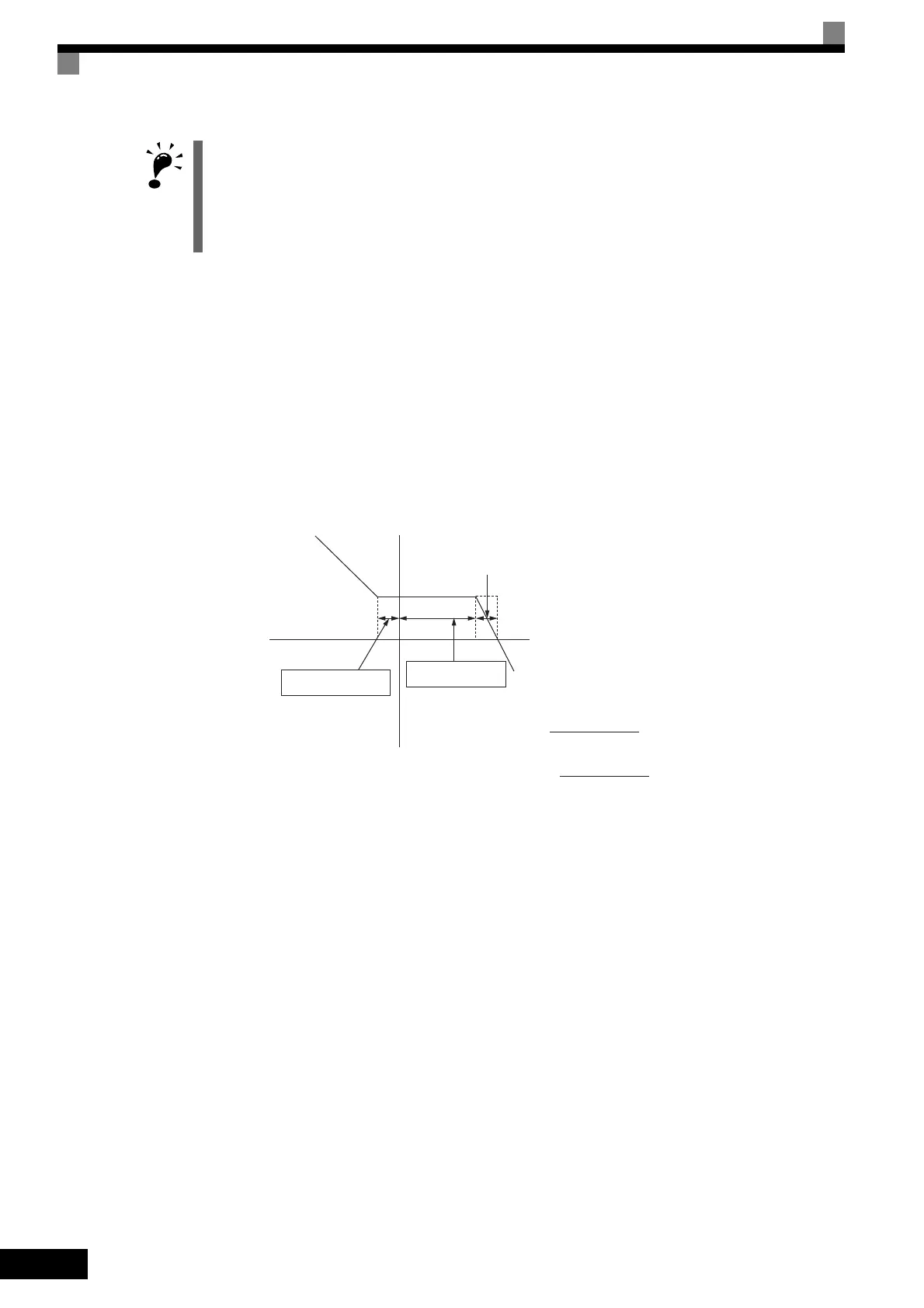
When the forward speed limit is set to 50% and the speed limit bias to 10%, the torque control range will be as
shown in the figure below unless the priority circuit is taken into consideration.
Fig 6.69 Setting Speed Limit Bias
Torque Limit Operation Examples
Operation examples will be described separately for winding operation, in which the speed and motor torque
are in the same directions, and rewinding operation, in which the speed and motor torque are in opposite direc-
tions.
Winding Operation
In a winding operation, the line (speed) and torque generated by the motor are in the same direction. For the
winding operation, both the speed limit and the torque reference input are positive. The motor will accelerate
when the torque reference input is larger than the load and will decelerate when it is smaller than the load. If
the motor turns faster than the speed limit, a negative compensation value is output from the speed limiter cir-
cuit. When the speed then drops below the speed limit, a positive compensation value is output. The torque
compensation is proportional to the ASR proportional gain. When the sum of the torque reference and the
torque compensation output by the speed limiter is the same as the actual load, the motor will stop accelerating
and run at a constant speed.
The direction in which speed is controlled is determined by the sign of the speed limit signal and the direction
of the Run Command.
• Positive voltage applied: The speed in the forward direction will be limited for forward operation.
• Negative voltage applied: The speed in the reverse direction will be limited for reverse operation.
If the direction of motor rotation and the command direction are not the same, speed will be limited to 0 as
long as b5-05 is set to 0.
ΔN %
ΔN will be set as follows
At motoring operation:
At regenerative operation: The smaller vaue
Forward torque
Forward runReverse run
Reverse torque
Torque reference [%]
C5-01
Torque reference [%]
C5-04
or d5-05
Speed limit bias
d5-05 10 %
Forward speed limit
d5-04 50 %
 Loading...


