7-4
UV2
控制回路
欠电压
Control Power Fault
The control power supply voltage
dropped.
• The wiring of the control power cir-
cuit is incorrect.
• A Backup Capacitor Unit for
Momentary Power Loss is not
attached to a 200 V/400 V Class
Inverter of 7.5 kW or less and the
value of the Momentary power loss
ridethru time (L2-02) factory setting
has been changed to the larger
value.
• Try turning the power supply
off and on.
• Replace the Inverter if the fault
continues to occur.
• Attach a Backup Capacitor Unit
for Momentary Power Loss.
UV3
冲击防止
回路故障
Inrush Prevention Circuit Fault
A fault occurred in the surge preven-
tion circuit.
The magnetic contactor did not
respond for 10 s even though the mag-
netic contactor ON signal has been
output.
• The magnetic contactor in the main
circuit failed.
• The magnetic contactor excitation
coil is burned out.
• Try turning the power supply
off and on.
• Replace the Inverter if the fault
continues to occur.
PF
输入缺相
Main Circuit Voltage Fault
The main circuit DC voltage oscillates
unusually (not when regenerating).
This fault is detected if a load is
greater than approximately 80% of the
maximum motor capacity.
This fault is detected when L8-05 is
set to 1.
• An open-phase occurred in the input
power supply.
• A momentary power loss occurred.
• The wiring terminals for the input
power supply are loose.
• The voltage fluctuations in the input
power supply are too large.
• The voltage balance between phases
is bad.
Reset the fault after correcting its
cause.
LF
输出缺相
Output Open-phase
An open-phase occurred at the
Inverter output.
This fault is detected when L8-07 is
set to 1 or 2
• There is a broken wire in the output
cable.
• There is a broken wire in the motor-
winding.
• The output terminals are loose.
Reset the fault after correcting its
cause.
The motor being used has a capacity
less than 5% of the rated output cur-
rent.
Check the motor and Inverter
capacity.
OH
(OH1)
散热片
过热
Cooling Fin Overheating
The temperature of the Inverter's cool-
ing fins exceeded the setting in L8-02
or the overheat protection level.
OH: The temperature exceeded the
setting in L8-02 (Stopping method can
be changed by L8-03.).
OH1: The temperature exceeded
100°C (Stopping method: Coast to
stop).
The ambient temperature is too high. Install a cooling unit.
There is a heat source nearby. Remove the heat source.
The Inverter's cooling fan has stopped.
Replace the cooling fan. (Contact
our sales representative.)
• A short-circuit between +V, −
V, and
AC terminals occu
rred.
• Overload in the control circuit ter-
minal.
• Make sure that i
ncorrect wiring
has not been done.
• Check the resistance and wir-
ing for the frequency setting
potentiometer, etc. (Check that
the current for terminals +V and
–V is 20 mA or less.)
Inverter's Cooling Fan Fault
(200 V Class: 7.5 kW or more,
400 V Class: 5.5 kW or more)
This fault is detected when L8-32 is
set to 1.
• The Inverter's cooling fan has
stopped.
• The heatsink is clogged.
• Replace the cooling fan. (Con-
tact our sales representative.)
• Clean the heatsink.
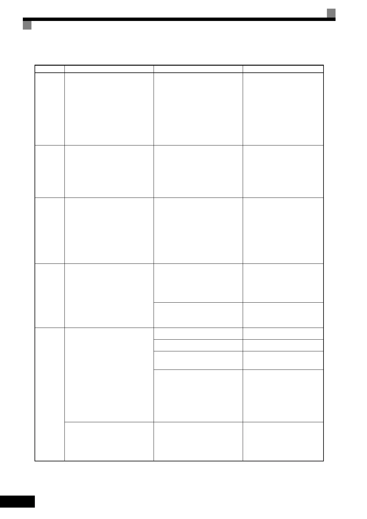
Table 7.1 Fault Displays and Processing (Continued)
Display Meaning Probable Causes Corrective Actions
 Loading...


