Protective and Diagnostic Functions
7-13
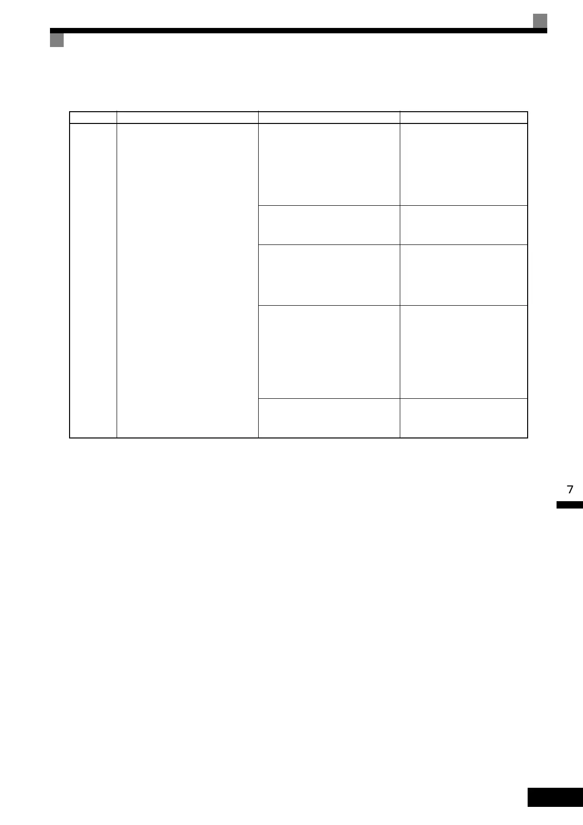
Table 7.2 Causes and Corrective Actions When the Digital Operator Goes Dark
Display Meaning Probable Causes Corrective Actions
操作器
熄灭
There was a drop in control power
voltage.
• A short-circuit between +V, −V, and
AC terminals occurred.
• Overload in the control circuit ter-
minal.
• Make sure that incorrect wiring
has not been done.
• Check the resistance and wir-
ing for the frequency setting
potentiometer, etc. (Check that
the current for terminals +V and
–V is 20 mA or less.)
The short-circuit bar between +1 and
+2 terminals in the main circuit has
been removed.
Attach the short-circuit bar.
P terminal and N terminal of the Brak-
ing Unit are connected in reverse.
• Check the wiring for the Brak-
ing Unit, including cables con-
nected to the Braking Unit and
relay terminals.
• Replace the Inverter.
Control power circuit failure
Charge indicator is lit:
• Replace the Digital Operator.
• Replace the board or the
Inverter.
Charge indicator is not lit:
• Check the input power supply
voltage.
• Replace the Inverter.
Malfunction occurred in the control
power circuit.
Turn OFF the power, wait for 5
minutes, and turn ON the power
again.
 Loading...


