10-36
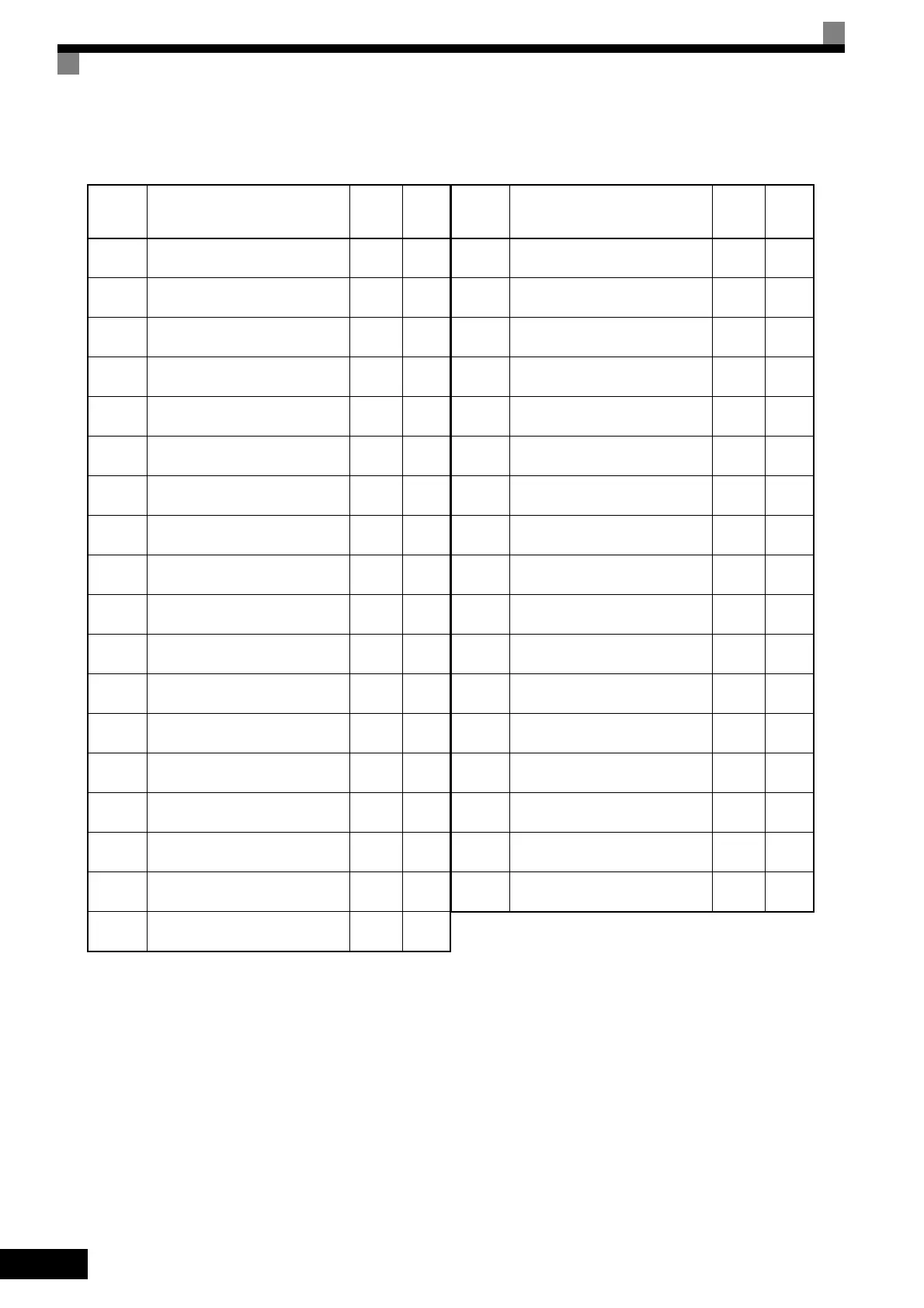
Table 10.7 User Constants (Continued)
* 1. Not initialized. (Japanese standard specifications: A1-00 = 1, A1-02 = 2)
* 2. When the control method is changed, the factory setting will change. The open-loop vector 1 factory settings are given.
* 3. The factory setting is 1.0 when using flux vector control.
* 4. The factory setting is 2.00 s when Inverter capacity is 55 kW min.
The factory setting will change when the control method is changed. The open-loop vector 1 factory setting is given.
* 5. By setting E2-11 (Motor rated output) the appropriate value will be set.
* 6. The factory settings depend on the Inverter capacity. The values for a 200 V Class Inverter of 0.4 kW are given.
* 7. When the control method is changed, the factory settings will change. The flux vector factory settings are given.
* 8. This constant can be monitored or set only when F is set for C6-02.
* 9. These are values for a 200 V Class Inverter. Values for a 400 V Class Inverter are double.
* 10.E1-11 and E1-12 are disregarded when set to 0.0.
* 11.E1-13 is set to the same value as E1-05 by autotuning.
* 12.The same capacity as that of the Inverter will be set if the constants are initialized.
* 13.If a current exceeding 110% of the Inverter rated current flows through the unit, the carrier frequency will automatically decrease and electromagnetic noise will
occur.
* 14.The factory settings in the parentheses are for 3-wire sequence.
* 15.If the setting is 0, the axis will accelerate to the specified speed for the specified acceleration time (C1-01 to C1-08).
N4-32
Speed estimator gain fluctuation
frequency 1
5.0
N4-33
Speed estimator gain fluctuation
frequency 2
20.0
N4-34
Speed estimator gain fluctuation
rate
200.0
N5-01 Feed forward control selection
0
*7
N5-02 Motor acceleration time
0.178
*6
N5-03 Feed forward proportional gain 1.0
o1-01 Monitor selection 6
o1-02 Monitor selection after power up 1
o1-03
Frequency units of reference set-
ting and monitor
0
o1-04
Setting unit for frequency con-
stants related to V/f characteristics
0
o1-05 LCD brightness adjustment 3
o2-01
LOCAL/REMOTE key enable/dis-
able
1
o2-02
STOP key during control circuit
terminal operation
1
o2-03 User constant initial value 0
o2-04 kVA selection
0
*6
o2-05
Frequency reference setting
method selection
0
o2-06
Operation selection when digital
operator is disconnected
0
o2-07 Cumulative operation time setting 0
No. Name
Fac-
tory
Setting
Set-
ting
o2-08
Cumulative operation time selec-
tion
0
o2-10 Fan operation time setting 0
o2-12
Fault trace/fault history clear func-
tion
0
o2-14
Output power monitor clear selec-
tion
0
o2-18
Capacitor maintenance setting 0
o3-01 Copy function selection 0
o3-02 Read permitted selection 0
T1-00 Motor 1/2 selection 1
T1-01 Autotuning mode selection
0
*2
T1-02 Motor output power
0.40
*6
T1-03 Motor rated voltage
200.0
*9
T1-04 Motor rated current
1.90
*6
T1-05 Motor base frequency 50.0
T1-06 Number of motor poles 4
T1-07 Motor base speed 1450
T1-08
PG pulses per revolution for teach-
ing
600
T1-09
Motor no-load current
1.20
*6
No. Name
Fac-
tory
Setting
Set-
ting
 Loading...


