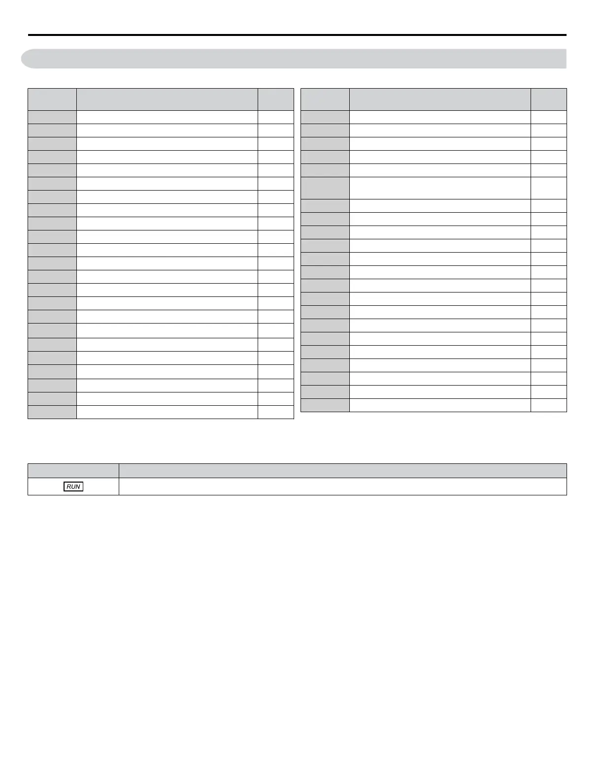
B.1 Parameter Groups
Table B.1 Parameter Groups
Parameter
Group
Name Page
A1 Initialization Parameters 313
b1 Operation Mode Selection 314
b2 DC Injection Braking and Short Circuit Braking 314
b3 Speed Search 314
b5 PI Control 315
C1 Acceleration and Deceleration Times 318
C2 S-Curve Characteristics 318
C4 Torque Compensation 318
C6 Carrier Frequency 318
d1 Frequency Reference 319
d2 Frequency Upper/Lower Limits 319
d3 Jump Frequency 319
E1 V/f Pattern for Motor 1 321
E2 Motor 1 Parameters 321
F6 Drive/Bypass Communications 322
H1 Multi-Function Digital Inputs 323
H2
<1>
Multi-Function Digital Outputs 324
H3 Multi-Function Analog Inputs 325
H4 Multi-Function Analog Outputs 165
H5
<2>
MEMOBUS/Modbus Serial Communication 327
L1 Motor Protection 328
L2 Momentary Power Loss Ride-Thru 328
L3 Stall Prevention 328
Parameter
Group
Name Page
L4 Speed Detection 329
L5 Fault Restart 329
L6 Torque Detection 330
L8 Drive Protection 330
n1 Hunting Prevention 331
n3
High Slip Braking (HSB) and Overexcitation
Braking
331
o1 HOA Keypad Display Selection 332
o2 HOA Keypad Functions 332
o4 Maintenance Monitor Settings 333
S1 Dynamic Noise Control Function 334
S2 Sequence Timer Operation 334
T1 Induction Motor Auto-Tuning 336
UB Bypass Control Monitors 338
U1 Operation Status Monitors 339
U2 Fault Trace 341
U3 Fault History 342
U4 Maintenance Monitors 344
U5 PI Monitors 345
Z1 Bypass Control System 347
Z2 Bypass Control Input/Output 351
Z3 Bypass Control Communication 352
Z4 Bypass Control Option Boards 354
<1> Available in bypass controller software versions VST800298 and later.
<2> Available in bypass controller software versions VST800297 and earlier.
Table B.2 Symbols and Icons Used in Parameter Descriptions
Symbol Description
Parameter can be changed during run.
B.1 Parameter Groups
312
YASKAWA ELECTRIC SIEP YAIZ1B 01E YASKAWA AC Drive – Z1000 Bypass Technical Manual

 Loading...


