u
Bypass Control Board LEDs
The bypass control board A2 has six bi-color LEDs.
The operational states of the bypass LEDs after completion of the power-up diagnostic LED sequence are described in Table
4.2. Wait at least 2 seconds for the power-up diagnostic process to complete before verifying LED states.
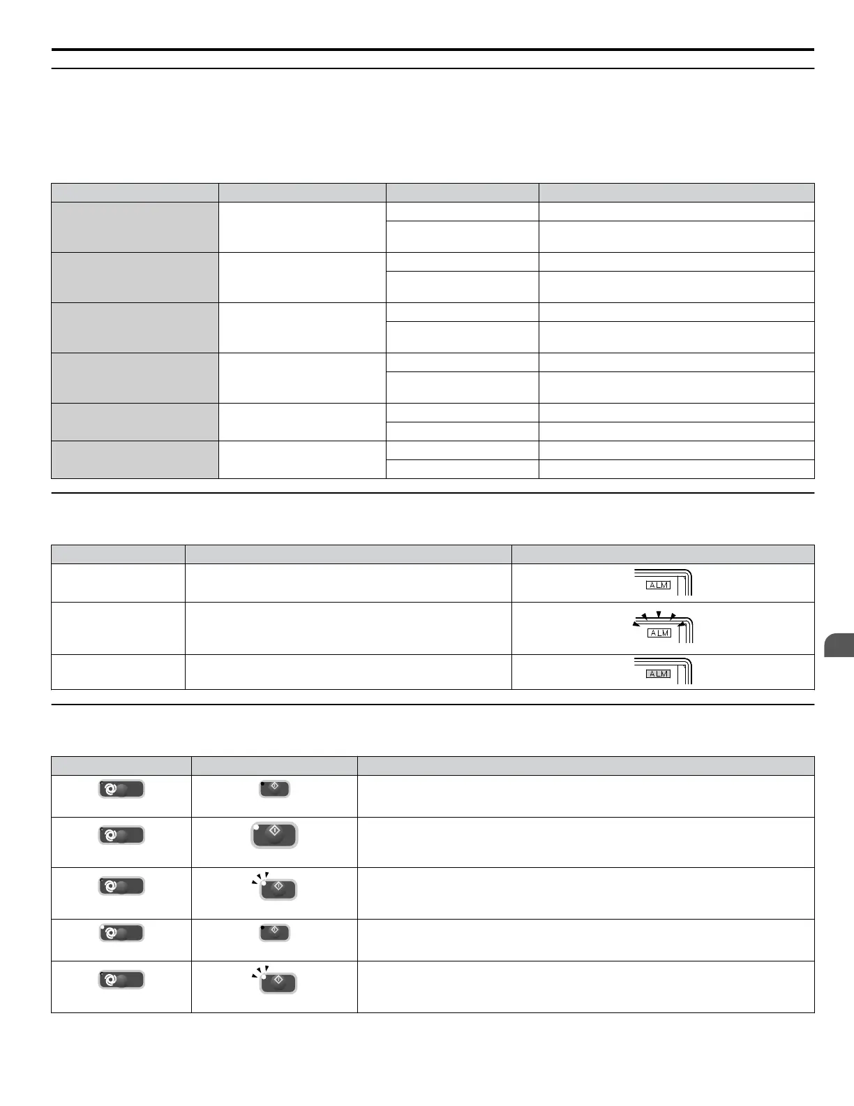
Table 4.2 Bypass Control Board LED States
Name Description Color Behavior
MS Module Status
Red Not used
Green
Turns ON when transmitting
Turns OFF when receiving
NS Network Status
Red Not used
Green
Turns ON when transmitting
Turns OFF when receiving
ST1 ST1, Status 1
Red Not used
Green
Round status
Toggles ON/OFF every 500 rounds
ST2 ST2, Status 2
Red Not used
Green
Scan status
Toggles ON/OFF every 500 scans
ST3 ST3, Status 3
Red Not used
Green Not used
ST4 ST4, Status 4
Red Not used
Green Not used
u
ALARM (ALM) LED Displays
Table 4.3 ALARM (ALM) LED Status and Contents
State Content Display
Illuminated When the drive detects an alarm or error.
Flashing
• When an alarm occurs.
• When an oPE is detected.
• When a fault or error occurs during Auto-Tuning.
Off Normal operation (no fault or alarm).
u
AUTO LED and HAND LED Indications
Table 4.4 AUTO LED and HAND LED Indications
AUTO LED HAND LED State
Off
Off
OFF mode
Off
On solid
HAND mode (Also during DC injection braking)
Off
Long blink (50% duty)
HAND mode when the Frequency Reference is 0 and/or decelerating in HAND mode, or
during PI Sleep or Snooze.
On solid
Off
Running in AUTO mode (Also during DC injection braking)
Off
Short blink (15% duty)
HAND mode, Ready, No Run command input.
Note: Short Blink for Legacy Operation Mode (S5-04 = 0).
4.2 Using the HOA Keypad
YASKAWA ELECTRIC SIEP YAIZ1B 01E YASKAWA AC Drive – Z1000 Bypass Technical Manual
95
4
Start-Up Programming
& Operation

 Loading...


