3.14 Connecting Wires to the 16-CH Temperature/Voltage Input Module
3.
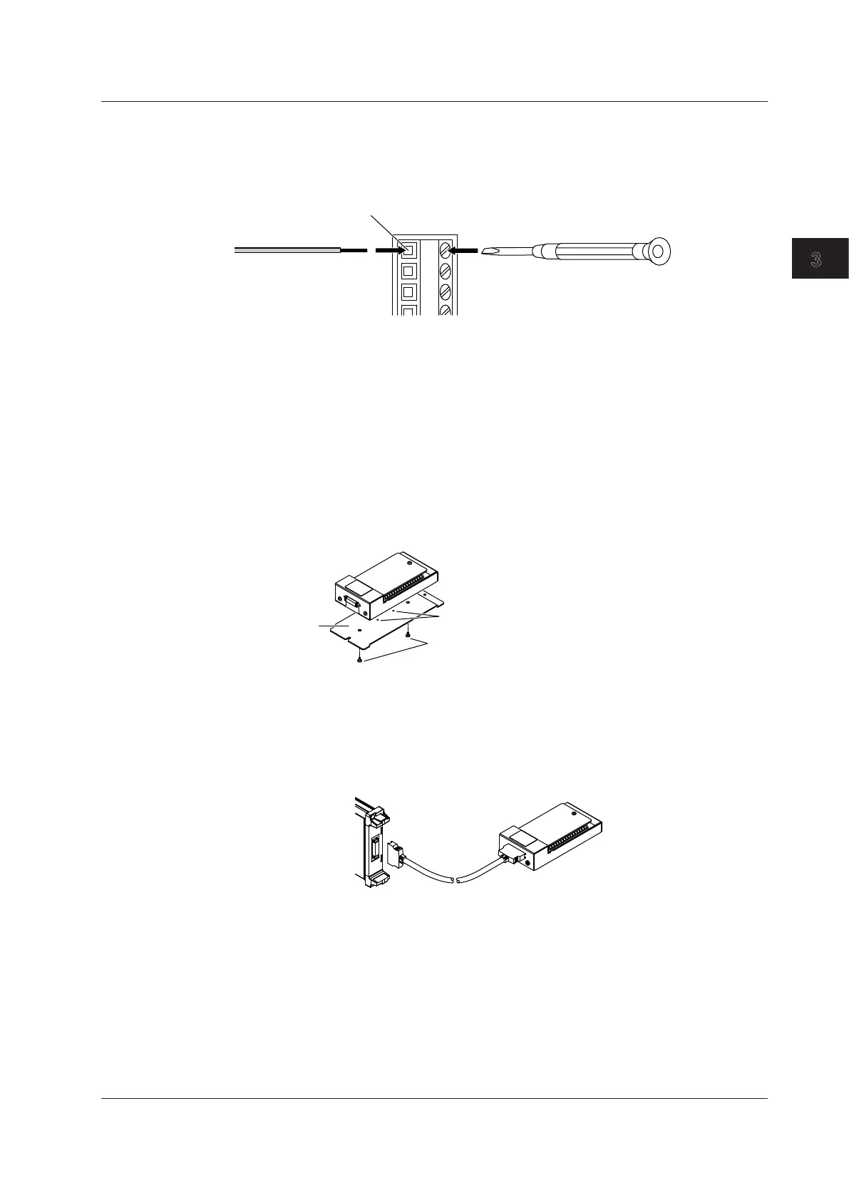
Loosen the terminal block screw using a flat-blade screwdriver.
4.
Insert the thermocouple or wire that you prepared into the wire insertion hole.
Insert the thermocouple or wire until its end reaches the back of the wire insertion hole.
5.
Tighten the terminal block screw using a flat-blade screwdriver.
Terminal block
Flat-blade Screwdriver
Wire
6.
Pull lightly on the wire to make sure that it doesn’t come out.
7.
Insert the protection cover into the guide hole.
8.
Tighten the protection cover screw using a screwdriver.
Fixing the Device in Place
If necessary, you can use the accessory attaching plate, B8074LN, to fix the scanner box to the panel.
1.
Align the small holes on the bottom side of the scanner box to the small projections of the
attaching plate.
2.
Screw the scanner box and the attaching plate together using the accessory binding screws
(M4 × 5 mm).
Screw tightening torque: 1.2 N•m
Binding screws
(M4 x 5 mm)
Attaching plate
B8074LN
Projections
Connecting the 16-CH Temperature/Voltage Input Module and the
Scanner Box
Using the cable that came with the scanner box (701953), connect the 720221 (16CH TEMP/VOLT)
and the scanner box.
Cable
701953
16-CH Temperature/Voltage
Input Module
720221 (16CH TEMP/VOLT)
3-53
IM DL850E-03EN
Making Preparations for Measurements
3

 Loading...


