3.12 Connecting Sensors to the Frequency Module
Sensors and Signal Output Sources That Can Be Connected
The table below shows the sensor and signal output source that can be connected. Appropriate input
presets are provided for each sensor and signal output source. For information about presets, see
Input Setup in section 1.7, “Configuring Frequency, Revolution, Period, Duty Cycle, Power Supply
Frequency, Pulse Width, Pulse Integration, and Velocity Measurements,” in the user’s manual.
Sensor and Signal Output Source Preset Name
5-V logic signal, 5-V output sensor, and sensor with TTL output Logic 5V
3-V logic signal and 3-V output sensor Logic 3V
12-V driven relay/sequence circuit and 12-V driven sensor Logic 12V
24-V driven relay/sequence circuit and 24-V driven sensor Logic 24V
Sensor/Encoder that outputs positive and negative voltages and sensor that outputs sine waves ZeroCross
100-VAC power supply (connected through the isolated probe (700929 or 701947) or passive
probe 702902)
AC100V
200-VAC power supply (connected through the isolated probe (700929 or 701947) or passive
probe 702902)
AC200V
Power-generating electromagnetic pickup EM Pickup
Open collector (0 to 5 V) output sensor, contact output Pull-up 5V
*
* For the internal equivalent circuit when the preset setting is Pull-up 5V, see the “Frequency Measurement”
section in chapter 2, “Vertical Axis” in the feature’s guide (IM DL850E-01EN).
WARNING
If over-range is indicated, the DL850E/DL850EV may be receiving a voltage higher than the
observed waveform or measured waveform values. To prevent electric shock, change the
vertical scale with the SCALE knob so that the entire amplitude of the waveform is displayed
within the waveform display area, and check the input voltage level.
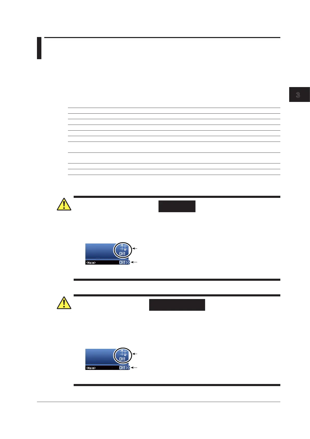
Over-range indication
Indicates the number of the channel that over-range is occurring on.
Channel indication when over-range is occurring on multiple channels
Indicates the smallest number among the channels that over-range is
French
AVERTISSEMENT
En cas de dépassement de plage, le DL850E/DL850EV risque de recevoir une tension
supérieure à la forme d’onde observée ou aux valeurs de forme d’onde mesurées. Pour éviter
tout risque de choc électrique, modifier l’échelle de gain vertical à l’aide du bouton SCALE, de
sorte que l’amplitude entière de la forme d’onde s’affiche sur l’afficheur, et vérifier le niveau de
tension d’entrée.
Dépassement de plage
Indique le numéro de canal sur lequel le dépassement de plage a lieu.
L’indication du canal en cas de dépassement
de plage sur des canaux multiples
Indique le numéro le plus petit parmi les canaux
sur lequel le dépassement a lieu.
3-45
IM DL850E-03EN
Making Preparations for Measurements
3

 Loading...


