3.16 Connecting a Cable to the CAN & LIN Bus
Monitor Module
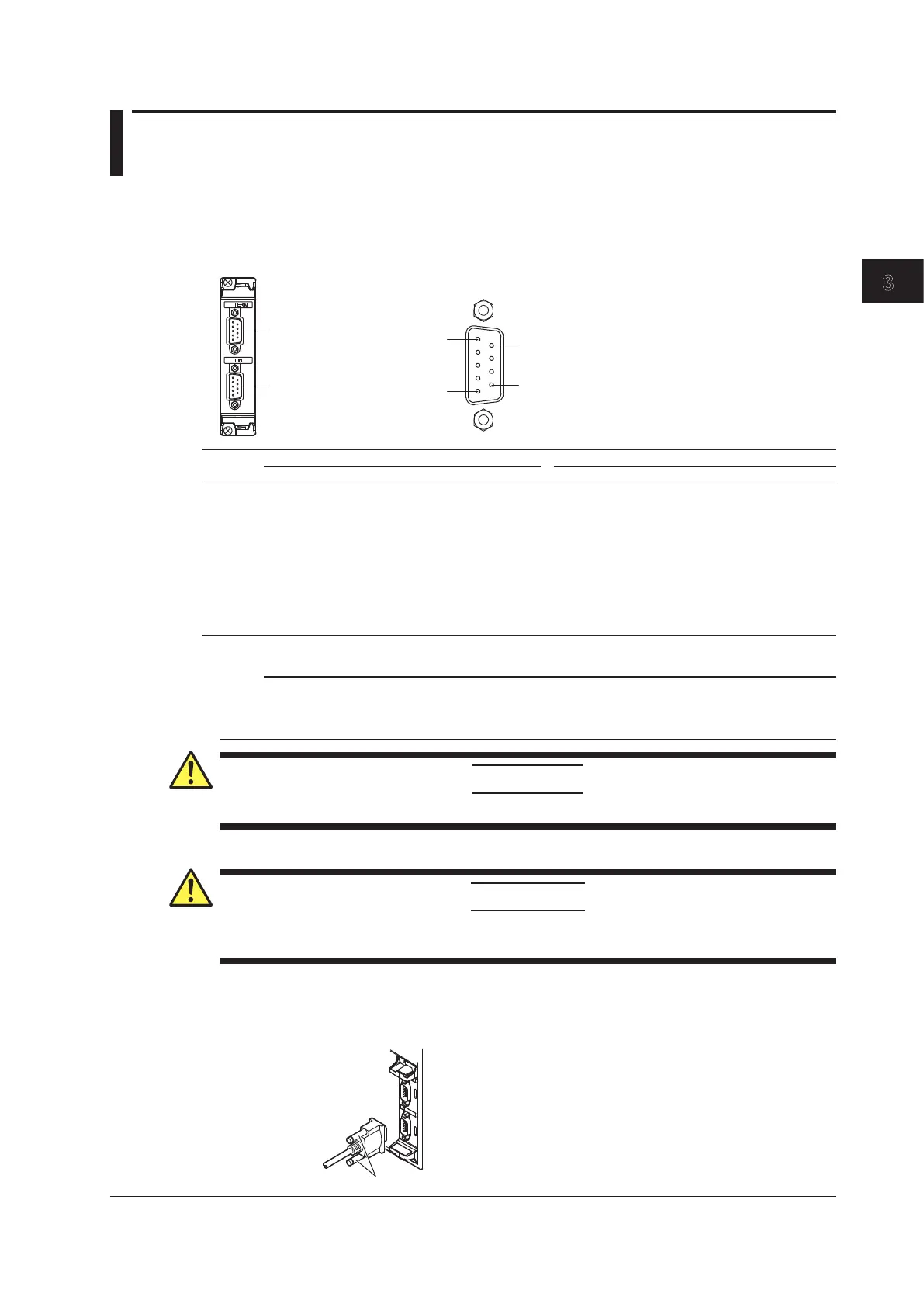
To monitor CAN bus signals, connect a cable to the CAN bus monitor module’s D-sub connector.
Connector Pinout
The pinout of the D-sub connector (9 pin, male) is shown below.
1
5
Pinout
CAN bus signal input terminal
LIN bus signal input terminal
CAN bus signal input terminal LIN bus signal input terminal
Pin No. Signal Function Signal Function
1 (NC) Not used (can not be connected to) LIN LIN signal
2 CAN_L CAN low signal (NC) Not used (can not be connected to)
3 CAN_GND Ground LIN_GND Ground
4 (NC) Not used (can not be connected to) VBAT Battery supply voltage
5 (NC) Not used (can not be connected to) (NC) Not used (can not be connected to)
6 CAN_GND Ground LIN_GND Ground
7 CAN_H CAN high signal (NC) Not used (can not be connected to)
8 (NC) Not used (can not be connected to) (NC) Not used (can not be connected to)
9 (NC) Not used (can not be connected to) (NC) Not used (can not be connected to)
* One-inch screws (number 4-40 UNC) are used.
Note
The shell of the CAN bus signal input connector is connected to CAN_GND. The shell of the LIN bus signal
input connector is connected to LIN_GND. Additionally, CAN_GND and its connector shell and LIN_GND and
its connector shell are isolated from the electric potential of the DL850E/DL850EV case (earth).
CAUTION
Applying a voltage greater than the maximum input voltage may damage the input section.
French
ATTENTION
Le fait d’appliquer une tension dépassant la tension d’entrée maximale risque d’endommager
la section d’entrée.
Connecting the Cable (Signal wires)
When you connect a cable to the D-sub connector, be sure to tighten the screws to ensure that the
cable is connected securely.
CAN & LIN bus monitor module
720241 (CAN & LIN)
Cable
3-55
IM DL850E-03EN
Making Preparations for Measurements
3

 Loading...


