App-29
IM DL850E-03EN
Appendix
App
Appendix 6 Block Diagrams
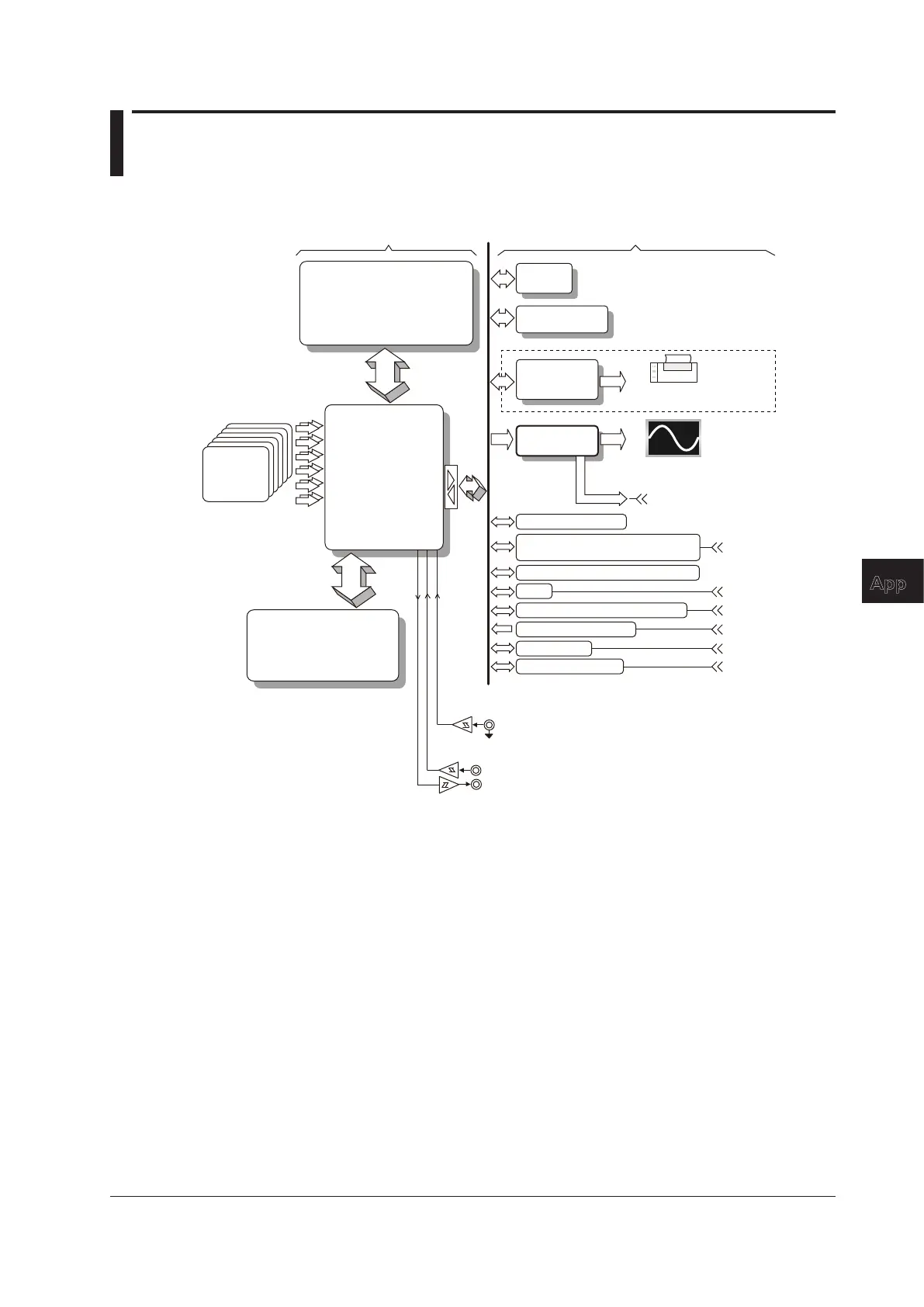
Block Diagram of the DL850E/DL850EV
Acquisition Block Diagram
CPU
ACQ Memory
GIGAZoom
Engine2
(ACQ-ASIC)
SD Memory Card
Printer
Controller
(/B5 option)
External HDD, eSATA support
(/HD0 option
2
)
Internal HDD (/HD1 option
2
)
USB
1000 BASE-LAN
GP-IB (/C1 or /C20 option
3
)
GP-IB Port
IRIG (/C20 option
3
)
IRIG Terminal
Main Memory
10.4 Color TFT
XGA 1024 × 768
Internal Thermal
Printer (100 mm width)
VIDEO OUT (XGA)
Ethernet Port
USB Port
GO/NO-GO
GO/NO-GO Port
Ext. Clk In
Ext. trig In/out
Plug-in
Module
CH1-CH16
Graphic
Controller
Real Time Math
(including Digital Filter)
(/G3 option)
250 Mpoint - 2 Gpoint
(/M1 or /M2
option
1
)
1 The /M1 and /M2 options cannot be installed
on the same instrument.
2 The /HD0 and /HD1 options cannot be
installed on the same instrument.
3 The /C1 and /C20 options cannot be installed
Signal Flow of the DL850E/DL850EV
The input terminal signal flow varies for each model. In this example, we will explain the signal flow
for the High-Speed 10 MS/s, 12-Bit Isolation Module, 701250 (HS10 M12). (For the signal flow of a
particular module, see the module’s block diagram.)
The input signal applied to the two input terminals is first processed by each module’s input section.
In the 701250 (HS10 M12), the signal is attenuated and amplified by an attenuator (ATT) and
amplifier (AMP). Then, the signal’s bandwidth is limited by a filter (FLT). Next, the signal is sampled
at a rate of 10 MS/s (10,000,000 times a second) by an A/D converter and converted into digital
data. Then, the signal passes through an isolator and an ASIC to a waveform-processing ASIC
(ACQ-ASIC).
The 16 channel of digital data that is sent to the CPU board passes through the GIGAZoom Engine2
waveform processor and is stored to the acquisition memory (ACQ Memory). The digital data stored
to the ACQ memory is compressed quickly by the GIGAZoom Engine2, and then it passes through
a graphic controller and is shown on the XGA TFT color display.
The realtime math feature (/G3 option) uses the A/D converted data of the analog input channels
or the math results of realtime math channels or both as its math sources and performs math
operations on the specified channels in real time.
You can use the DL850E/DL850EV to perform realtime math on up to 16 channels at the same
time.

 Loading...


