App-35
IM DL850E-03EN
Appendix
App
Item Specifications
• When in duty cycle measurement mode
8
Dependent on the input frequency
Input frequency of 1 kHz or less: ±0.1%
Input frequency of 1 kHz to 10 kHz: ±0.2%
Input frequency of 10 kHz to 50 kHz: ±1.0%
Input frequency of 50 kHz to 100 kHz: ±2.0%
Input frequency of 100 kHz to 200 kHz
:
±4.0%
• When in pulse width measurement mode
8
Measurement accuracy is specified according to the measurement range and input pulse width
[Definition of measurement accuracy]
±(0.05% of 10 div + accuracy dependent on the input pulse width)
[Accuracy dependent on the input pulse width]
Input pulse width of 500 µs or greater: 0.05% of the input pulse width
Input pulse width of 100 µs to 500 µs: 0.1% of the input pulse width
Input pulse width of 50 µs to 100 µs: 0.3% of the input pulse width
Input pulse width of 50 µs or less: 0.5% of the input pulse width + 0.1 µs
Input voltage range (±FS) When using 1:1 probe attenuation: ±1 V, ±2 V, ±5 V, ±10 V, ±20 V, ±50 V (±FS)
Input impedance 1 MΩ ± 1 approx. 35 pF
Pull-up function: 4.7 kΩ, approx. 5 V (pull-up can be turned ON only when the
input is set to Pull-up 5 V)
Input coupling settings AC, DC
Probe attenuation setting 10:1, 1:1
Minimum voltage width for pulse
detection
200 mV
P-P
Bandwidth limit Select from Full, 100 kHz, 10 kHz, 1 kHz, and 100 Hz
Cutoff characteristics: −12 dB/OCT (Typical
9
)
Threshold Set within the FS of the voltage range. Set in units of 1% of the FS.
Hysteresis Select ±1%, ±2.5%, or ±5% of the FS of the voltage range
Preset function Logic (5 V/3 V/12 V/24 V), electromagnetic pickup, zero crossing, pull-up, AC100 V, AC200 V,
and user-defined
Slope selection Select rising or falling
Lower −3 dB point when AC
coupled
0.5 Hz or less (0.05 Hz or less when using the 700929 or 702902, 0.005 Hz or less when
using the 701947) (Typical
9
)
Chatter elimination function OFF or 1 to 1000 ms (1 ms resolution)
Eliminates the chatter that occurs such when the contact input is turned ON/OFF.
Can discard the signal changes over the specified interval.
Input status indication function Input status indication through the LEDs of each channel function
When in operation: Illuminates in green when pulse input is detected
When overdriven: Illuminates in red when the input voltage exceeds the range
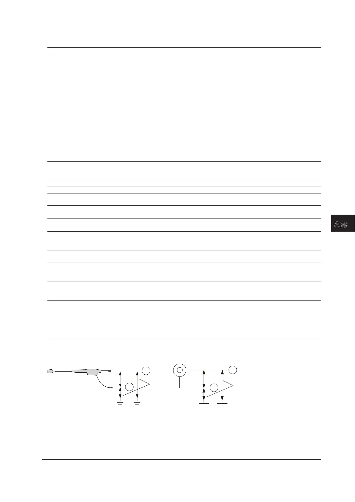
Compatible probes/cables Connection cable (1:1): Recommended 1
366926
Voltage probe: Recommended 2
700929 (10:1 safety probe), 20 to 45 pF
702902 (10:1 safety probe), 25 to 40 pF
701947 (100:1 probe), 15 to 45 pF
1 Value measured under standard operating conditions.
H
L
Combined with the 700929, 702902, or 701947
2
700929
702902
701947
H
L
Combined with the (701901 + 701954) or
direct input (cable that does not comply with the safety standards)
4
5
BNC
Withstand voltage: 1500 Vrms for 1 minute
Allowable transient surge voltage (between earth and input): ±2100 Vpeak
3
6 Input waveform of 1 Vpp, rectangular wave, rise/fall time within 1 ms (input range: ±10 V, bandwidth limit: Full, and hysteresis: ±1%)
7 Input waveform of 90 Vrms, sine wave (input range: AC100 V, bandwidth limit 100 kHz, and hysteresis: ±1%)
8 Input waveform of 1 Vpp, rectangular wave, rise/fall time within 5 ns (input range: ±10 V, bandwidth limit: Full, and hysteresis: ±1%)
9 Typical value represents a typical or average value. It is not strictly warranted.
Appendix 8 Frequency Module (701280) Specifications

 Loading...


