Home
YOKOGAWA
Test Equipment
DL850E
YOKOGAWA DL850E User Manual
4
of 1
of 1 rating
228 pages
Give review
Manual
Specs
To Next Page
To Next Page
To Previous Page
To Previous Page
Loading...
1-6
IM DL850E-03EN
GPS Interface Model
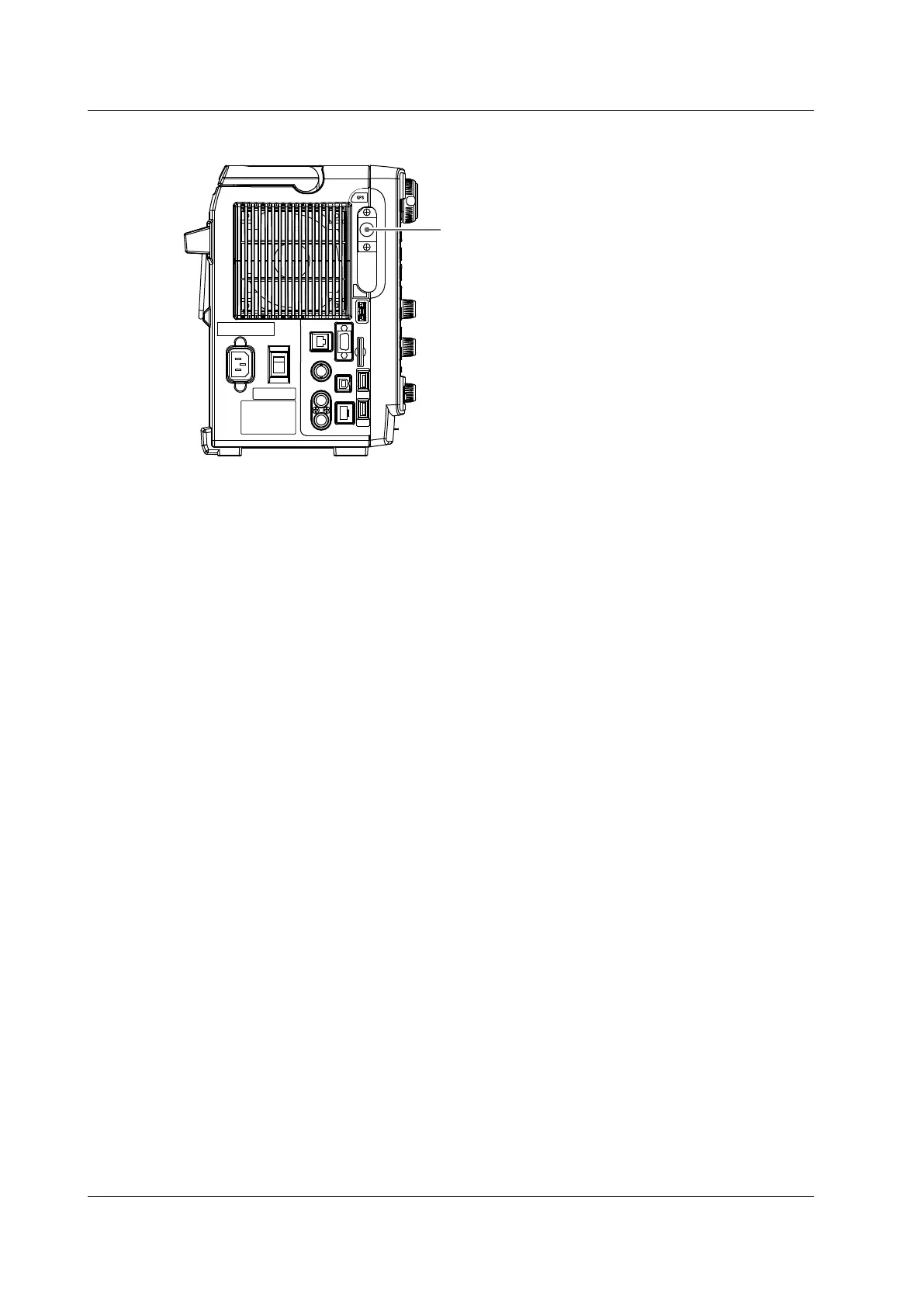
Only the parts that are different from the standard model are shown below
.
GPS input terminal (optional)
Use this terminal to apply external sync signals.
Explanation about how to use → Section 3.19 (/C30)
1.1 T
op Panel, Front Panel, Right Side Panel, and Left Side Panel
29
31
Table of Contents
Default Chapter
1
Getting Started Guide
1
Product Registration
2
List of Manuals
3
Regarding the Conventional DL850 and DL850V
5
Checking the Contents of the Package
6
Standard Accessories
8
Safety Precautions
15
Sales in each Country or Region
20
Symbols and Notation Used in this Manual
21
Table of Contents
22
Chapter 1 Names and Functions of Parts
25
Top Panel, Front Panel, Right Side Panel, and Left Side Panel
25
Universal (Voltage/Temp.)
27
Vent
29
Panel Keys and Knobs
31
Shift Key
34
Screens
35
System Configuration
37
Chapter 2 Main Features
38
Vertical and Horizontal Axes
38
Triggering
41
Waveform Acquisition
44
Hard Disk Recording
45
Waveform Display
47
Waveform Computation and Analysis
48
Chapter 3 Making Preparations for Measurements
50
Handling Precautions
50
Installing the Instrument
52
Installing Input Modules
55
Connecting to a Power Supply and Turning the Power Switch on and off
60
Connecting the Power Cord
61
Connecting Probes
66
Correcting the Probe Phase
77
Connecting Measurement Leads
79
Connecting Thermocouples
83
Connecting Bridgeheads
85
Connecting a Logic Probe to the Logic Input Module
88
3.11 Connecting an Acceleration Sensor
91
3.12 Connecting Sensors to the Frequency Module
94
Connecting Wires to the 16-CH Voltage Input Module
96
Connecting Wires to the 16-CH Temperature/Voltage Input Module
99
Connecting a Cable to the CAN Bus Monitor Module
103
Connecting a Cable to the CAN & LIN Bus Monitor Module
104
3.17 Attaching the Panel Sheet
105
Loading Roll Paper into the Built-In Printer (Option)
106
Connecting an Antenna to the GPS Interface (Option)
108
Chapter 4 Common Operations
109
Key and Jog Shuttle Operations
109
Entering Values and Strings
111
Using USB Keyboards and Mouse Devices
113
Connection Procedure
114
Synchronizing the Clock
118
Performing Auto Setup
119
Initializing Settings
121
Setup Menu
121
Calibrating the DL850E/DL850EV
122
Starting and Stopping Waveform Acquisition
123
Displaying Help
124
Chapter 5 External Signal I/O
125
External Trigger Input (TRIGGER IN)
125
Trigger Output (TRIGGER OUT)
126
External Clock Input (EXT CLK IN)
128
Video Signal Output (VIDEO out (XGA))
129
GO/NO-GO Determination I/O and External Start/Stop Input (EXT I/O)
130
IRIG Signal Input (IRIG Option)
134
GPS Signal Input (GPS Option)
135
Chapter 6 Specifications
136
Signal Input Section
136
Triggering Section
136
Time Axis
138
Display
138
Features
139
Data Storage
140
Fft
147
Built-In Printer
147
6.10 Auxiliary I/O Section
149
6.11 Computer Interface
151
6.12 General Specifications
152
Index
152
6.13 Module Specifications
156
High-Speed 10 Ms/S, 12-Bit Isolation Module (701250)
156
High-Speed High-Resolution 1 Ms/S, 16-Bit Isolation Module (701251)
158
High-Speed 10 Ms/S, 12-Bit Non-Isolation Module (701255)
160
High-Voltage 100 Ks/S, 16-Bit Isolation Module (with RMS) (701267)
161
Universal (Voltage/Temp.) Module (701261) / Universal (Voltage/Temp.) Module (with AAF) (701262)
163
Temperature, High Precision Voltage Isolation Module (701265)
165
Strain Module (NDIS) (701270)
167
Acceleration/Voltage Module (with AAF) (701275)
171
Frequency Module (701281)
173
High-Speed 100 Ms/S, 12-Bit Isolation Module (720210 and 720211)
177
16-CH Voltage Input Module (720220)
179
16-CH Temperature/Voltage Input Module (720221)
180
Logic Input Module (720230)
182
CAN Bus Monitor Module (720240)
183
CAN & LIN Bus Monitor Module (720241)
184
SENT Monitor Module (720243)
185
4-CH 1 Ms/S, 16-Bit Isolation Module (720254)
186
6.14 Logic Probe Specifications
188
16-CH Scanner Box Specifications
190
External Dimensions
190
External Dimensions
191
Appendix
192
Appendix 1 Relationship between the Time Axis Setting, Record Length, and Sample Rate
193
Appendix
207
Relationship between the Main Channel Sample Rate, Sub Channel Data Update Rate, and Acquisition Memory Writing Rate
207
Appendix 3 Relationship between the Record Length and the Acquisition Mode
210
Appendix 4 Default Values
213
Appendix 5 USB Keyboard Key Assignments
219
Appendix 6 Block Diagrams
220
Appendix 7 High-Voltage 100 Ks/S, 16-Bit Isolation Module (with RMS) (701260) Specifications
223
Appendix 8 Frequency Module (701280) Specifications
225
4
Based on 1 rating
Ask a question
Give review
Questions and Answers:
Need help?
Do you have a question about the YOKOGAWA DL850E and is the answer not in the manual?
Ask a question
YOKOGAWA DL850E Specifications
General
Brand
YOKOGAWA
Model
DL850E
Category
Test Equipment
Language
English
Related product manuals
YOKOGAWA DL7440
501 pages
YOKOGAWA DL9040L
539 pages
YOKOGAWA DL9140L
539 pages
YOKOGAWA DLM3022
284 pages
YOKOGAWA DLM3054
284 pages
YOKOGAWA DLM5034
156 pages
YOKOGAWA DL 1540
201 pages
YOKOGAWA DL2700 Series
57 pages
YOKOGAWA DL6000 Series
388 pages
YOKOGAWA DLM2000 Series
340 pages
YOKOGAWA DLM 2000 Series
11 pages
YOKOGAWA ScopeCorder DL950
316 pages