Types of Input Modules
The following types of input modules are available.
High-Speed 10 MS/s, 12-Bit Isolation Module 701250 (HS10M12)
High-Speed High-Resolution 1 MS/s, 16-Bit Isolation Module 701251 (HS1M16)
High-Speed 10 MS/s, 12-Bit Non-Isolation Module 701255 (NONISO_10M12)
High-Voltage 100 kS/s, 16-Bit Isolation Module (with RMS) 701267 (HV (with RMS))
Universal (Voltage/Temp.) Module 701261 (UNIVERSAL)
Universal (Voltage/Temp.) Module (with AAF) 701262 (UNIVERSAL (AAF))
Temperature, High Precision Voltage Isolation Module 701265 (TEMP/HPV)
Strain Module (NDIS) 701270 (STRAIN_NDIS)
Strain Module (DSUB, Shunt-Cal) 701271 (STRAIN_DSUB)
Acceleration/Voltage Module (with AAF) 701275 (ACCL/VOLT)
Frequency Module 701281 (FREQ)
High-Speed 100 MS/s, 12-Bit Isolation Module 720210 (HS100M12)
High-Speed 100 MS/s, 12-Bit Isolation Module 720211 (HS100M12)
16-CH Voltage Input Module 720220 (16CH VOLT)
16-CH Temperature/Voltage Input Module 720221 (16CH TEMP/VOLT)
Logic Input Module 720230 (LOGIC)
CAN Bus Monitor Module
*
720240 (CAN MONITOR)
CAN & LIN Bus Monitor Module
*
720241 (CAN & LIN)
SENT Monitor Module* 720243 (SENT)
4-CH 1 MS/s, 16-Bit Isolation Module 720254 (4CH 1M16)
* The CAN bus monitor, CAN & LIN bus monitor, and SENT monitor modules can be used on the DL850EV. They
cannot be used on the DL850E.
Precautions to Be Taken When Installing or Removing Input
Modules
If you replace one installed input module with another, the settings for the channel will be reset to their
defaults when the power is turned on. If you want to keep the settings, specify a save destination and
save them.
Installation Procedure of Modules
1.
Make sure that the power switch on the left side panel of the instrument is turned off.
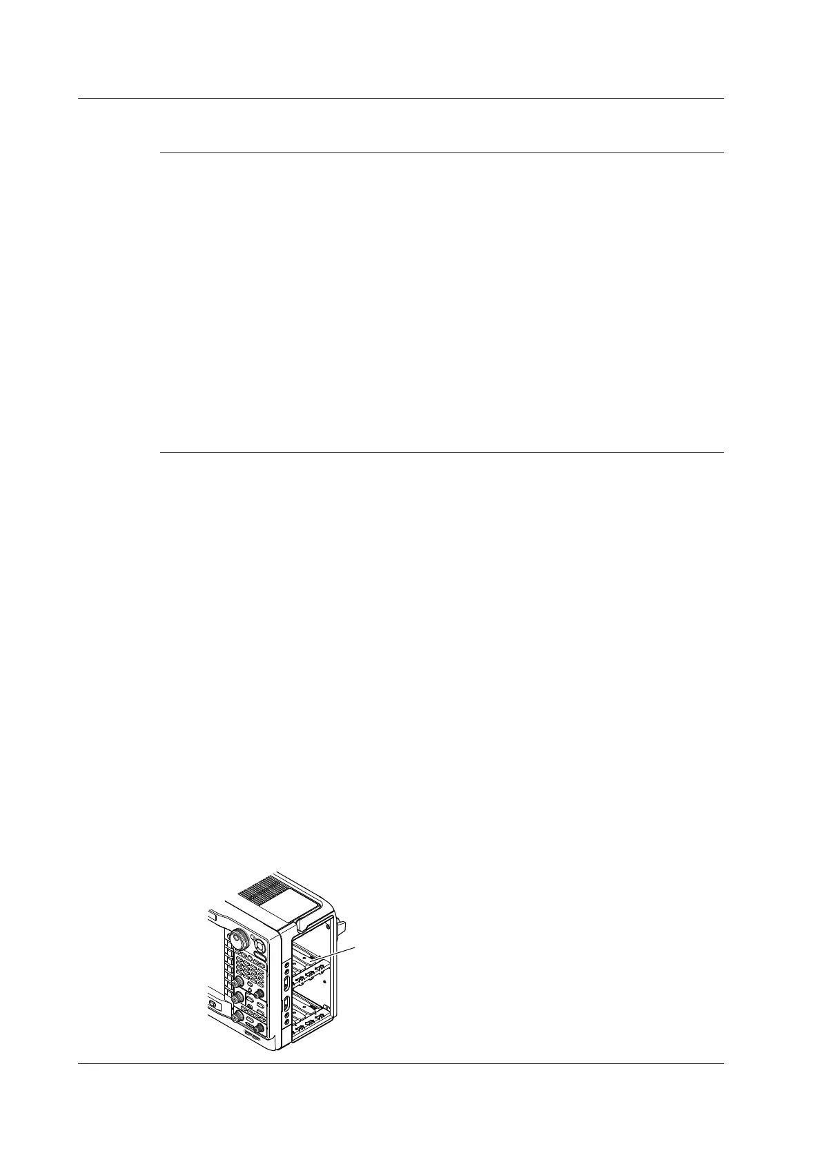
2.
Check the channel number displayed on the input module installation slot on the right side
panel of the instrument, and then install the input module along the guide.
Holding the handles on the top and bottom of the input module, press hard until it clicks in place.
If there is a cover panel on the slot in which to install the module, remove the cover panel, first.
3.
Firmly fasten the screws that came with the instrument in two places: the top and bottom of the
input module.
Screw tightening torque: 0.6 N•m
4.
Turn the instrument’s power switch on.
5.
In the overview screen, check that the name of the module that you installed is displayed
correctly at the appropriate slot. If it is not correct, remove the module according to the steps
in “Removal” shown below, and reinstall the module according to steps 1 to 3 shown above. To
display the overview screen, see section 19.4,
“
Viewing System Information (Overview),” in the
user’s manual.
3.3 Installing Input Modules
3-8
IM DL850E-03EN

 Loading...


