<9. Advanced Engineering >
As an example, the bitmap of the alarm data of NPAS_POU is described below.
- Example with high limit alarm (HI) detected for the NPAS POU
In the alarm bitmap of NPAS_POU, bit 15 maps to the high limit alarm (HI)
condition.
If only a high limit alarm (HI) is detected, only bit 15 is set to 1 to give bit pattern
“00000000000000001000000000000000”.
When converted to DWORD data type, this gives the alarm status value of
DWORD#00008000 for the NPAS POU.
- Example with high-high limit (HH) and high limit alarms (HI) detected
In this case, in addition to bit 15 for HI described above, bit 19 associated with
the high-high limit alarm (HH) is also set to 1 such that 2 bits are on concurrently.
The bit pattern is “00000000000010001000000000000000”, which converts to
the alarm status value of DWORD#00008000.
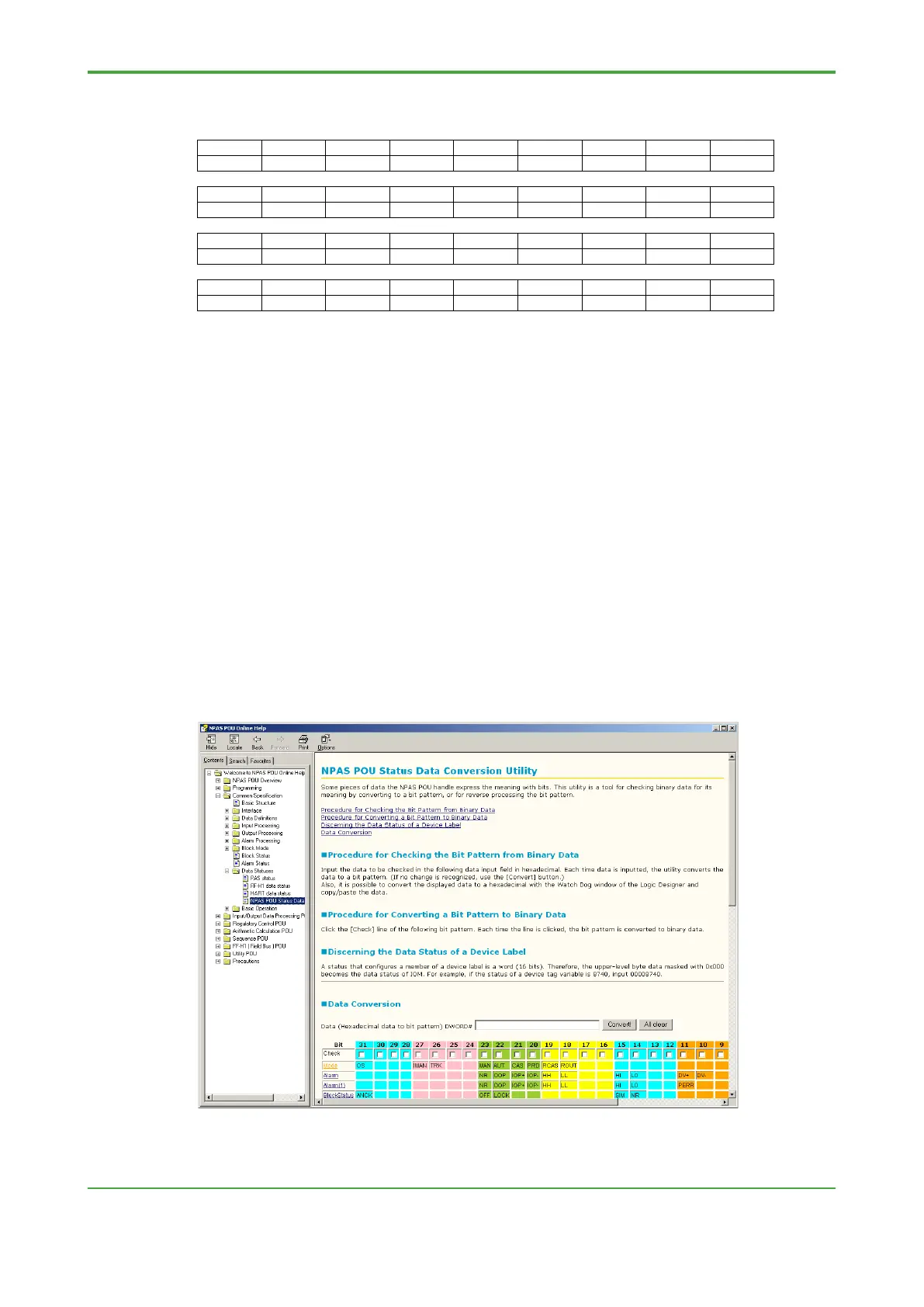
● How to Check Mode, Status and Alarm in Logic Designer
To check mode, status or alarm conditions of an NPAS POU in Logic Designer, you
can either use the Watch window or use the bit conversion utility described in the
NPAS POU online help documentation.
 Loading...


