<4. Control Application Creation>
Consider the example logic to be created below, which consists of multiple analog
inputs, NPAS_PIDs and analog outputs, as well as logic for setting MV to MAN, 0%,
PV value calculation processing and logic for writing SV value for the NPAS_PID.
This application can be segmented by function into four pieces: analog I/O and
NPAS_PID; logic for setting MV to MAN, 0%; PV value calculation processing and
logic for writing SV value.
The first option is to create one worksheet for each segment, as shown in
segmentation pattern A below.
Analog input
NPAS_PID
Analog output
MV=0% sequence logic
PV value calculation processing
Logic for writing SV value
Segmentation pattern A
Analog input
NPAS_PID
Analog output
MV=0% sequence logic
PV value calculation processing
Logic for writing SV value
Segmentation pattern B
Analog input
NPAS_PID
Analog output
MV=0% sequence logic
PV value calculation processing
Logic for writing SV value
Segmentation pattern C
Analog input
NPAS_PID
Analog output
MV=0% sequence logic
PV value calculation processing
Logic for writing SV value
Unsegmented worksheet
As the logic for setting MV=0% and logic for writing SV value are relatively simple,
including their codes into the same worksheet for analog I/O and NPAS_PID may
increase ease of understanding. This option for worksheet creation is shown in
segmentation pattern B above.
Over segmentation may sometimes lead to a more complicated application.
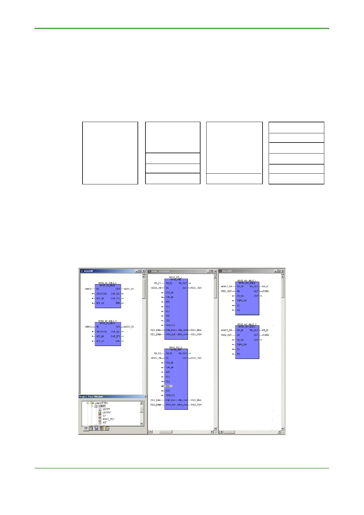
In segmentation pattern C, the analog I/O and NPAS_PID function is segmented into
three pieces, namely, analog input, NPAS_PID, analog output. The figure below
shows the actual view displayed in Logic Designer after creation.
 Loading...


