12-7
IM WT3001E-51EN
Voltage Fluctuation and Flicker Measurement (Option)
12
12.2 Setting the Voltage Fluctuation and Flicker Measurement Mode
Explanation
• Display Related to the Voltage Fluctuation and Flicker Measurement
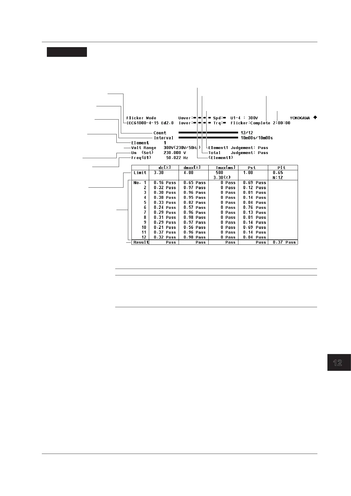
The figure below is a display example of normal flicker measurement.
Measured element
Measurement count
Observation period indicator
Judgement limit
Judgement by measurement item
Voltage frequency
Voltage range
(target voltage/target frequency)
Display element
Elapsed time in an
observation period
Rated voltage
Total judgement
Display element
judgement
Flicker
measurement status
Elapsed
measurement time
• Flicker Measurement Status
The following five flicker measurement statuses are available.
Display Meaning
Reset Condition in which the measured value is reset and initialization can be executed.
Initializing Initializing
Ready Initialized condition in which measurement can be started.
Start Measurement in progress. The elapsed time is displayed to the right.
Complete Complete
• Connecting to the Harmonic/Flicker Measurement Software
If you use the Harmonic/Flicker Measurement Software, this instrument automatically
switches to voltage fluctuation and flicker mode.
• Limitations on Changing the Measurement Mode
This instrument cannot switch to voltage fluctuation and flicker measurement mode in
the following conditions.
• When the master/slave synchronization measurement is set to slave.
• When the integration function is started or stopped.
• When auto print is ON.
• While storage or recall operation is in progress.
• While the storage medium is being accessed.
• While saving waveform sampling data to the storage medium.

 Loading...


