User’s Manual 1PH HYD3000-HYD6000-ZSS
Rev. 1.1 16/03/2021
Identification: MD-AL-GI-00
Rev. 1.1 of 16/03/2021 - Application: GID
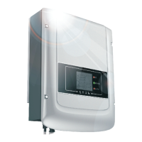
Figure 30 – Correct positioning of the current sensors for a system with two separate lines
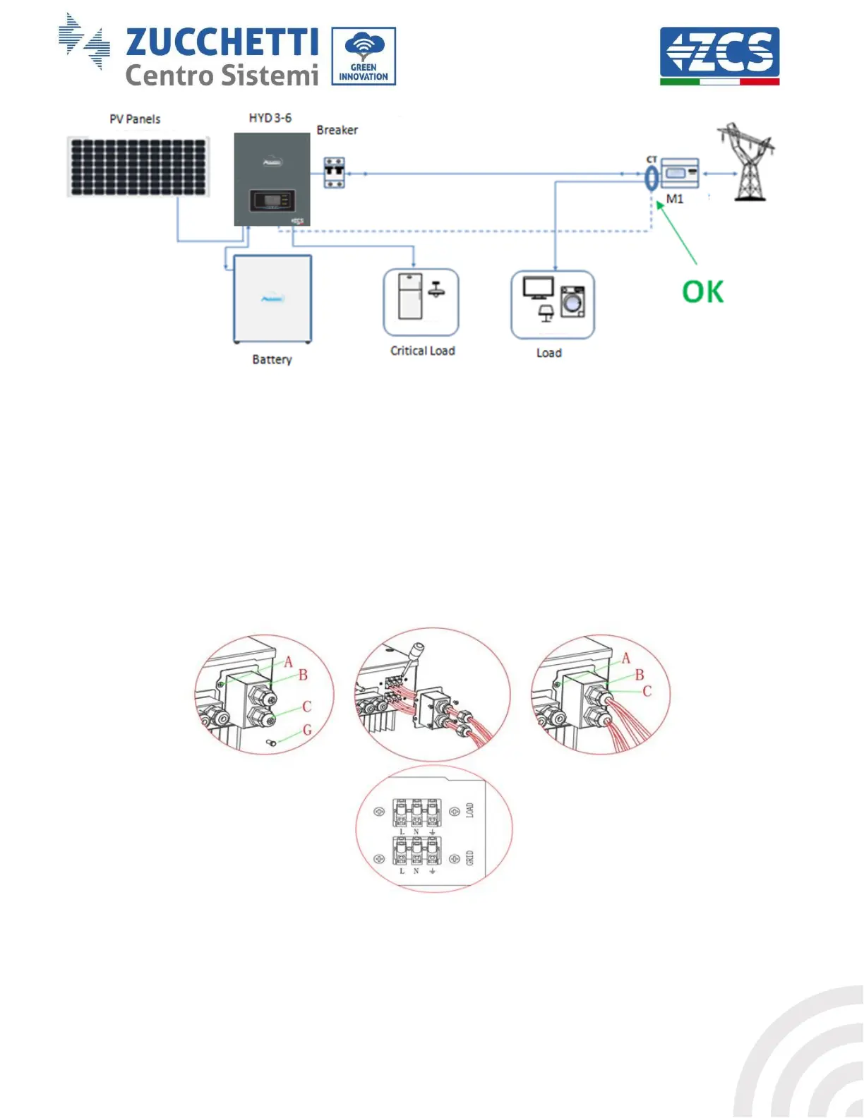
4.6. Grid connection
Step 1: Loosen the 4 screws (part A) using a screwdriver (fig. 15).
Step 2: Remove the waterproof cover (part B), loosen the cable gland (part C), and then remove the cap (part G).
Step 3: Route a three-pole cable through the GRID cable gland, then connect the three wires to the
corresponding terminal blocks. (BROWN - L, BLUE - N, YELLOW / GREEN - PE).
Step 4: Fasten the waterproof cover using the 4 screws.
Figure 31 – Connecting the grid and critical loads