P1075391-001 • ZQ520 Repair Procedures • 2-18 •
Printer Frame Assembly
Installation Instructions
This kit includes the parts necessary to install P1072539-012 Printer Frame
Assembly. Read these instructions thoroughly before attempting to install this kit.
Tools Required
• T-8 TORX Driver (4.7 +/- 1 in. lb.)
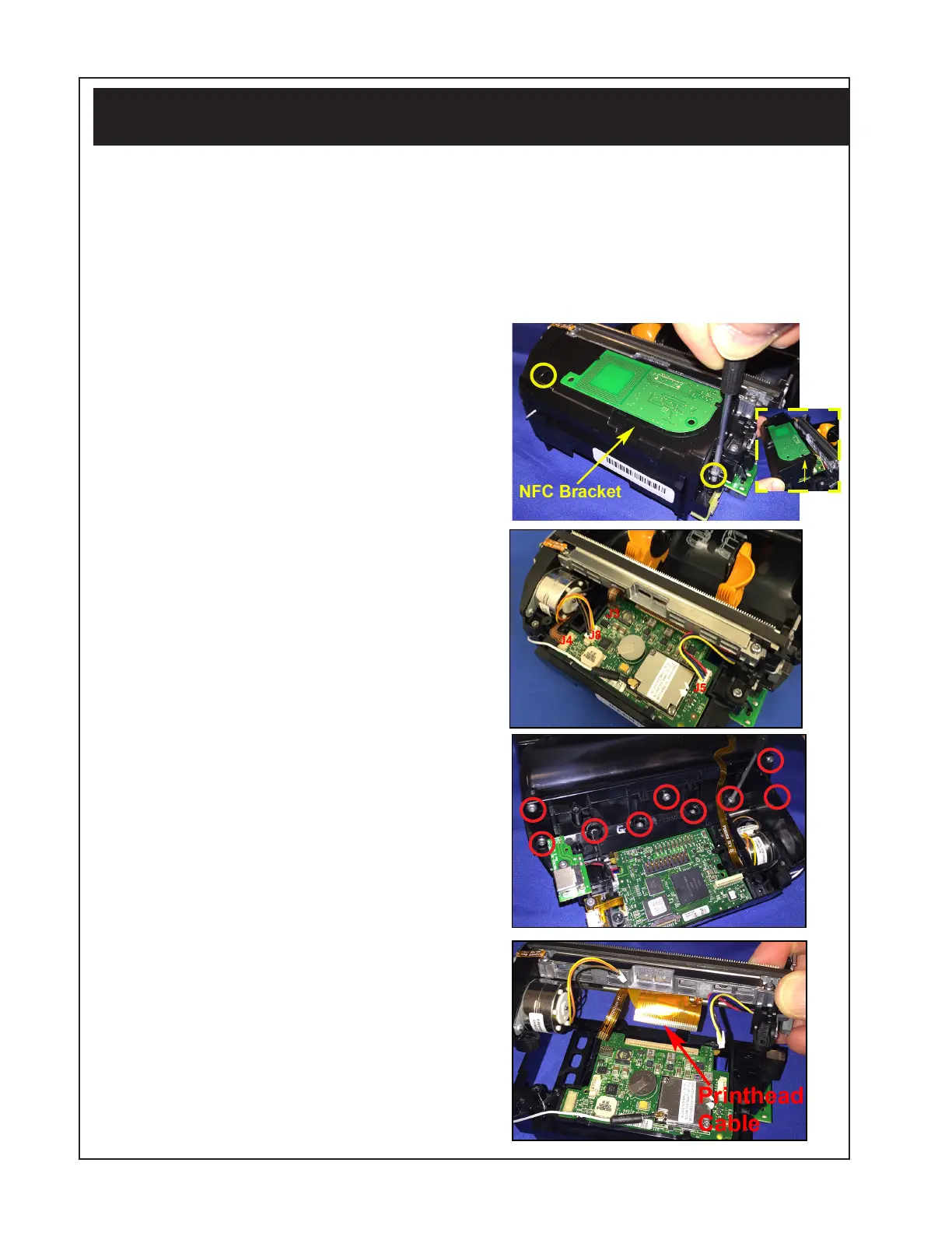
Removing the Printer Frame Assembly
1. Remove the Printer Chassis from
the Main Housing as described
above.
2. If printer has Active NFC, use a T-8
TORX driver to remove the two (2)
screws holding the NFC Bracket to
the PCBA Mounting Bracket.
3. Disconnect the Motor Cable (J8),
the Black Bar Cable (J4), the Gap
Sensor Cable (J3), and the Head Up
Cable (J5) on the Top PCBA.
4. Remove nine (9) screws located
on the PCBA Mounting Bracket
(where shown) with a T-8 TORX
driver.
5. Disconnect the Printhead Cable
from the MLB to separate the
Printer Frame from the PCBA
Mounting Bracket (as shown).
6. Reverse the procedure to
reassemble the Printer Frame.
 Loading...