P1075391-001 • ZQ520 Repair Procedures • 2-35 •
Main Logic Board (MLB) & Top PCBA
Installation Instructions
This kit includes the parts and documentation necessary to install the
P1063406-002 Main Logic Board (MLB) and P1063406-012 Top PCBA kits. Read
these instructions thoroughly before attempting to install this kit.
Tools Required: T-8 TORX Driver (2.5 +/- 1 in. lb.)
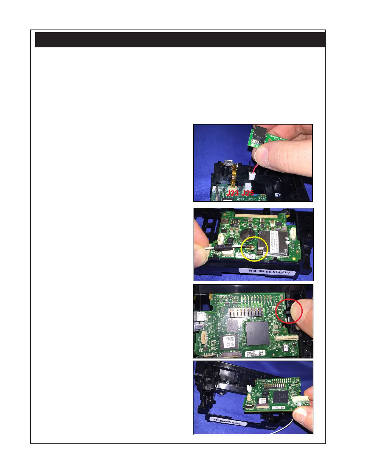
Removing the Main Logic Board
and Top PCBA
1. Remove the Printer Chassis from
the Main Housing as described on
Page 2-16.
2. Disassemble the printer as
previously described.
3. Disconnect the DC Jack Board
(J25) and Micro USB Board (J23)
from the on the MLB if you have
not done so already. Use a T-8
TORX driver to remove the one
screw securing each board to the
PCBA bracket.
4. Disconnect the radio antenna on
the Top PCBA (circled).
5. Press down on the plastic tab of
the PCBA Bracket (where shown)
which secures the MLB in the
bracket.
6. Press up on the Top PCBA to
snap the two boards out from the
bracket.
7. Disconnect the MLB from the Top
PCBA.
 Loading...