P1075391-001 • ZQ520 Repair Procedures • 2-37 •
DC Input Cable Connector Assembly
Installation Instructions
This kit includes the parts and documentation necessary to install the
P1063406-022 DC Input Cable Connector Assembly. Read these instructions
thoroughly before attempting to install this kit.
Tools Required: T-8 TORX Driver (2.5 +/- 1 in. lb.)
Removing the DC Input Cable
Connector Assembly
1. Remove the Printer Chassis from
the Main Housing as described on
Page 2-16.
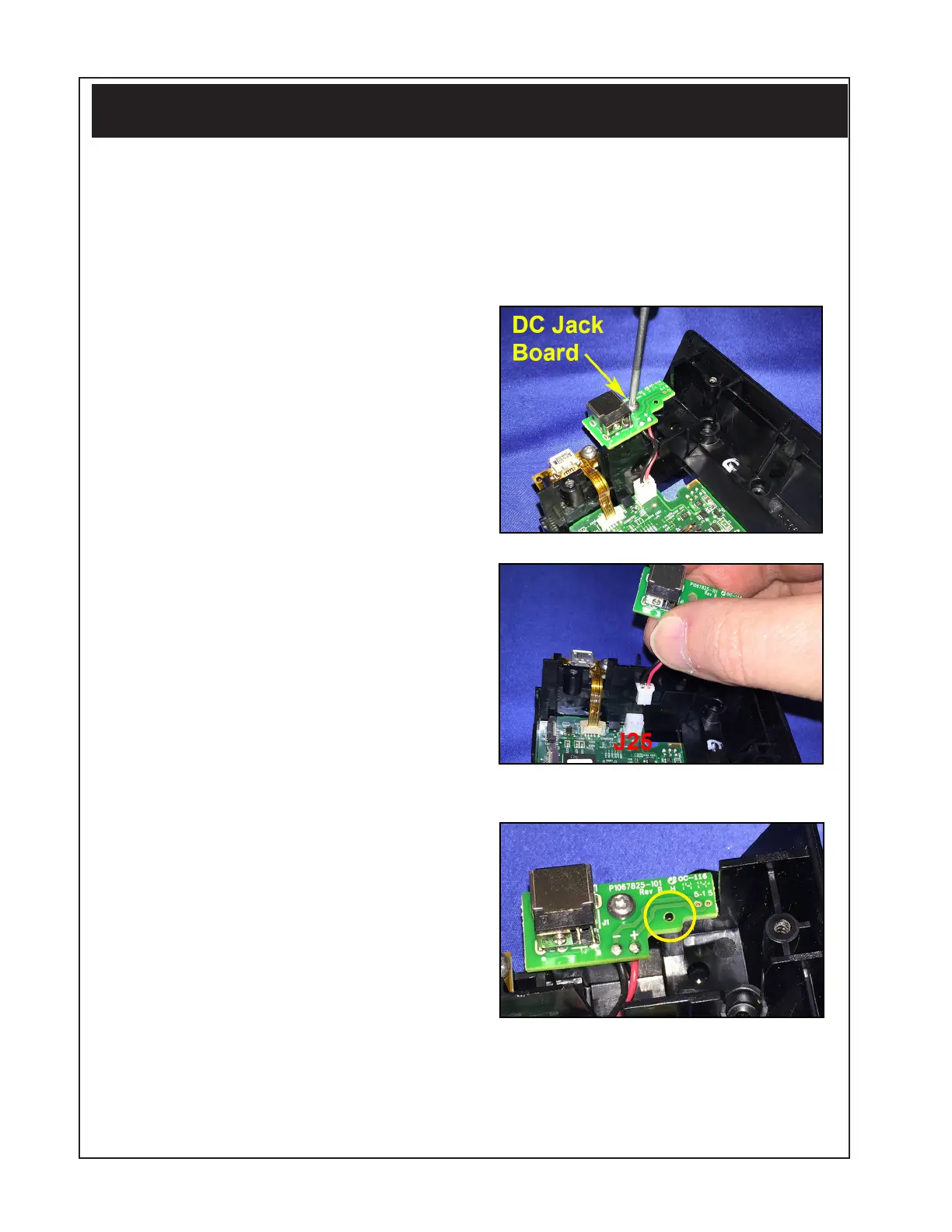
2. Locate the DC Input Cable
Connector Assembly on the
bottom of the chassis (where
shown).
3. Use a T-8 TORX driver to remove
the screw attaching the DC Jack
Board to the PCBA Bracket. (Set
aside the screw.)
4. Disconnect the DC Jack Cable
from J25 on the MLB to remove
the assembly.
Installing the DC Input Cable
Connector Assembly
1. Connect the DC Jack Cable to J25
on the MLB.
2. Insert the post on the PCBA
Bracket into the hole on the DC
Jack Board to properly align the
board (circled).
3. Secure the DC Jack Board to the
PCBA Bracket using the screw and
a T-8 driver (2.5 +/- in. lb.).
 Loading...