Service Kit Installation Procedures
4–64 www.zoll.com 906-0731-04-01 Rev. C
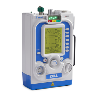
8 Remove any excess RTV from the case. Insert and
tighten the two 4-40 x 3/16 screws (provided in the
kit) holding the new USB Connector to the front
case.
Dress the USB Connector cable along the case and
over the SpO
2
flex cable.
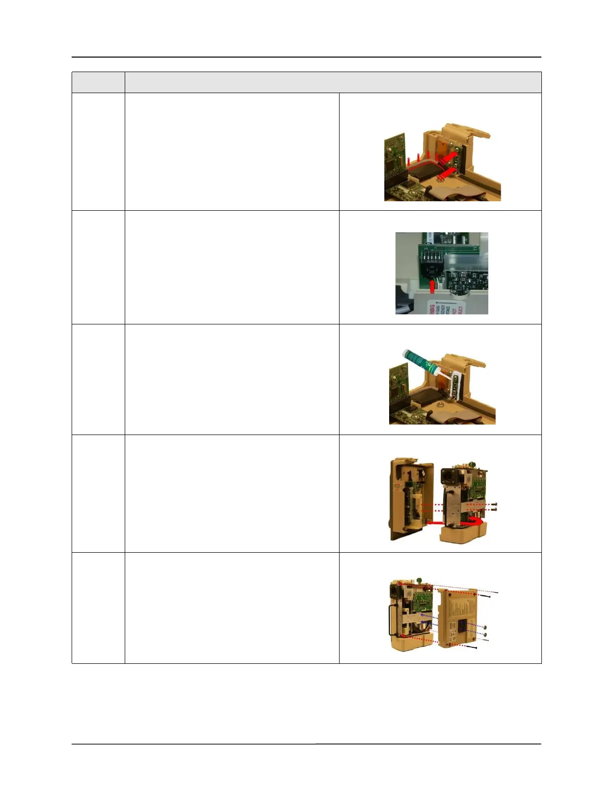
9 Attach USB Connector cable to its mating
connector on the CPU board.
Make sure tab locks the cable in place.
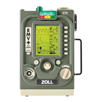
10 Apply RTV Sealant around USB board and allow to
dry.
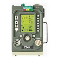
11 Place the front case assembly over the ventilator
module and tighten the two 4-40 x 1/4 screws to
the dovetail mounting bracket.
Reconnect the ribbon cable unto the PIM board.
Make sure the two ejector latches are secured.
12 Attach the back case to the ventilator module and
align cover with the handle, air intake housing, and
dovetail mounting studs.
Insert and tighten the two 10-32 Keps nuts
(provided in the kit) and the four 6-32 x 2” screws.
Step Action